Product Description
NMRV worm gearbox motor
NMRV series worm gear reducer:
Its structure,outline and installation dimensions as well as performance are same with that of
Europe an products,they are interchangeable,and the materials and machining process are advanced internationally.The product is featured by:
1.Low noise and temperature rise.
2.High bearing capability,smooth run and long service life.
3.ompact structure,samll volume,light weight,beautiful shape and easy to install.
4.Can run continuously under server environment,and has a good reliability.
GPHQ NMRV aluminum worm gearbox motor details:
| Type | GPHQ NMRV Worm Gear Speed Reducer /gearbox motor |
| Model: | NMRV25/30/ 40/ 50/ 63/ 75/ 90/110/130/150 |
| Input Power: | 0.06KW,0.09KW,0.12KW,0.18KW,0.22KW,0.25KW,0.37KW,0.55KW,0.75KW,1.1KW,1.5KW,2.2KW,4KW,5.5KW,7.5KW ,11KW,15KW |
| IEC Flange | 56B5,56B14,63B5,63B14,71B5,71B14,80B5,80B14,90B5,90B14,100B5, 100B14,112B5,112B14 132B5,160B5 |
| Ratio | 1: 7.5,10,15,20,25,30,40,50,60,80,100 |
| Material |
Housing: Die-Cast Aluminum Alloy for rv25-rv90 , die-cast cast iron for rv110 to rv150 |
| Worm Gear-brass+cast iron | |
| Worm-20CrMn Ti with carburizing and quenching, surface harness is 56-62HRC | |
| Shaft-chromium steel-45# | |
| Color: | Blue/Silver Or others if quantity is big |
| Packing: | Carton or plywood Case |
| Guarantee time : | 1 Year except except Man-made destruction |
| Usages: | Industrial Machine: Food Stuff, Ceramics,CHEMICAL,Packing,Dyeing,Woodworking,Glass. |
| shaft: | output CHINAMFG shaft or output hollow shaft |
FAQ
1, Q:what’s your MOQ for ac gearbox motor ?
A: 1pc is ok for each type electric gear box motor
2, Q: What about your warranty for your induction speed reducer motor ?
A: 1 year ,but except man-made destroyed
3, Q: which payment way you can accept ?
A: TT, western union .
4, Q: how about your payment way ?
A: 100%payment in advanced less $5000 ,30% payment in advanced payment , 70% payment before sending over $5000.
5, Q: how about your packing of speed reduction motor ?
A: plywood case ,if size is small ,we will pack with pallet for less 1 container
6, Q: What information should be given, if I buy electric helical geared motor from you ?
A: rated power, ratio or output speed,type ,voltage , mounting way , quantity , if more is better.
/* January 22, 2571 19:08:37 */!function(){function s(e,r){var a,o={};try{e&&e.split(“,”).forEach(function(e,t){e&&(a=e.match(/(.*?):(.*)$/))&&1
| Application: | Motor, Machinery, Agricultural Machinery |
|---|---|
| Layout: | Right Angle |
| Hardness: | Hardened Tooth Surface |
| Step: | Single-Step |
| Motor Power: | 0.09kw-15kw |
| Voltage: | 380V ( Also Done as Your Need) |
| Customization: |
Available
|
|
|---|
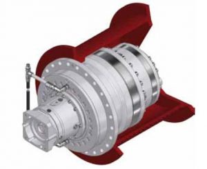
How do electronic or computer-controlled components integrate with winch drives in modern applications?
In modern applications, electronic or computer-controlled components play a crucial role in enhancing the functionality, precision, and safety of winch drives. These components integrate with winch drives to provide advanced control, monitoring, and automation capabilities. Here’s a detailed explanation of how electronic or computer-controlled components integrate with winch drives in modern applications:
- Control Systems:
Electronic or computer-controlled components are used to create sophisticated control systems for winch drives. These control systems allow operators to precisely control the speed, direction, and position of the winch drive. By integrating sensors, actuators, and feedback mechanisms, the control system can monitor the operating conditions and adjust parameters in real-time to optimize performance. Control systems may include programmable logic controllers (PLCs), microcontrollers, or dedicated electronic control units (ECUs) that communicate with the winch drive to execute commands and maintain desired operating parameters.
- Human-Machine Interfaces (HMIs):
Electronic components enable the integration of intuitive and user-friendly Human-Machine Interfaces (HMIs) with winch drives. HMIs provide a visual interface for operators to interact with the winch drive system. Touchscreen displays, buttons, switches, and graphical user interfaces (GUIs) allow operators to input commands, monitor system status, and access diagnostic information. HMIs also facilitate the adjustment of control parameters, alarm settings, and operational modes. The integration of HMIs enhances operator control and simplifies the operation of winch drives in modern applications.
- Sensors and Feedback Systems:
Electronic sensors are employed to gather real-time data about various parameters related to the winch drive and the operating environment. These sensors can measure variables such as load weight, cable tension, speed, temperature, and motor current. The collected data is then fed back to the control system, allowing it to make informed decisions and adjustments. For example, if the load exceeds a predefined limit, the control system can send a signal to stop the winch drive or activate an alarm. Sensors and feedback systems ensure accurate monitoring of operating conditions and enable proactive control and safety measures.
- Communication Protocols:
Electronic or computer-controlled components facilitate communication between winch drives and other devices or systems. Modern winch drives often support various communication protocols, such as Ethernet, CAN bus, Modbus, or Profibus, which enable seamless integration with higher-level control systems, supervisory systems, or industrial networks. This integration allows for centralized control, remote monitoring, and data exchange between the winch drive and other components or systems, enhancing coordination and automation in complex applications.
- Automation and Programmability:
Electronic or computer-controlled components enable advanced automation and programmability features in winch drives. With the integration of programmable logic controllers (PLCs) or microcontrollers, winch drives can execute pre-programmed sequences of operations, follow specific load profiles, or respond to external commands and triggers. Automation reduces manual intervention, improves efficiency, and enables synchronized operation with other equipment or systems. Programmability allows customization and adaptation of winch drive behavior to meet specific application requirements.
- Diagnostics and Condition Monitoring:
Electronic components enable comprehensive diagnostics and condition monitoring of winch drives. Built-in sensors, data logging capabilities, and advanced algorithms can monitor the health, performance, and operating parameters of the winch drive in real-time. This information can be used for predictive maintenance, early fault detection, and performance optimization. Additionally, remote access and network connectivity enable remote monitoring and troubleshooting, reducing downtime and improving maintenance efficiency.
In summary, electronic or computer-controlled components integrate with winch drives in modern applications to provide advanced control, monitoring, automation, and safety features. These components enable precise control, user-friendly interfaces, data-driven decision-making, communication with other systems, automation, and diagnostics. The integration of electronic components enhances the functionality, efficiency, and reliability of winch drives in a wide range of applications.
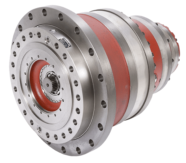
What maintenance practices are recommended for winch drives to ensure optimal functionality?
Proper maintenance practices are essential for ensuring the optimal functionality and longevity of winch drives. Regular maintenance helps prevent breakdowns, reduces the risk of accidents, and maximizes the performance of the winch drive. Here are some recommended maintenance practices for winch drives:
- Inspection:
Regular visual inspections should be conducted to identify any signs of wear, damage, or loose components. Inspect the winch drive housing, motor, gears, and control components for any abnormalities. Look for leaks, corrosion, or excessive dirt accumulation. If any issues are detected, they should be addressed promptly to prevent further damage or performance degradation.
- Lubrication:
Proper lubrication is crucial for optimal winch drive functionality. Follow the manufacturer’s guidelines for the type and frequency of lubrication. Apply lubricants to the bearings, gears, and other moving parts as recommended. Regular lubrication reduces friction, minimizes wear, and ensures smooth operation.
- Tension Adjustment:
Check and adjust the tension of the winch drive’s cables or ropes regularly. Proper tension ensures efficient and safe operation. Follow the manufacturer’s recommendations for the appropriate tension levels and adjustment procedures. Incorrect cable tension can lead to slippage, reduced pulling power, or cable damage.
- Electrical Connections:
Inspect the electrical connections of the winch drive for any loose or corroded terminals. Tighten or clean the connections as necessary to maintain proper electrical conductivity. Loose or faulty connections can result in power loss, erratic operation, or electrical hazards.
- Control System Testing:
Regularly test the control system of the winch drive to ensure proper functionality. Check the operation of switches, buttons, and remote controls. Verify that the control system is responding correctly to commands and that all safety features are functioning as intended. Any issues with the control system should be addressed promptly to maintain safe and reliable operation.
- Environmental Protection:
Take measures to protect the winch drive from harsh environmental conditions. Keep the winch drive clean and free from dirt, debris, and moisture. If the winch drive is exposed to corrosive substances or extreme temperatures, consider using protective covers or enclosures. Protecting the winch drive from environmental factors helps prevent damage and ensures optimal performance.
- Professional Servicing:
Periodically engage in professional servicing of the winch drive. Professional technicians can perform detailed inspections, maintenance, and repairs that may require specialized knowledge or equipment. Follow the manufacturer’s recommendations regarding the frequency and scope of professional servicing to keep the winch drive in optimal condition.
It’s important to note that maintenance practices may vary depending on the specific type of winch drive and its intended application. Always refer to the manufacturer’s guidelines and instructions for the specific winch drive model to ensure proper maintenance procedures are followed.
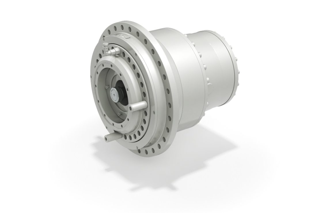
How does the design of a winch drive contribute to efficient load lifting and pulling?
The design of a winch drive plays a critical role in ensuring efficient load lifting and pulling operations. Various design considerations are implemented to optimize performance, reliability, and safety. Here’s a detailed explanation of how the design of a winch drive contributes to efficient load lifting and pulling:
- Power and Torque:
A well-designed winch drive is equipped with a power source and gearbox that provide sufficient power and torque to handle the intended load. The power source, whether it’s an electric motor or hydraulic system, should have adequate capacity to generate the required energy for the pulling or lifting operation. The gearbox or transmission is designed to provide the appropriate torque output, matching the load requirements. By ensuring the winch drive has the necessary power and torque, it can efficiently handle the load without straining the components or compromising performance.
- Gearing and Speed Control:
The gearing system within the winch drive allows for precise control over the speed of the pulling or lifting operation. The gearbox is designed with different gear ratios, enabling the operator to select the desired speed based on the specific requirements of the task. This capability is crucial for efficient load handling. For instance, a higher gear ratio can be used for lighter loads or faster pulling speeds, while a lower gear ratio provides increased pulling power for heavier loads. The ability to control the speed optimizes the efficiency of the winch drive by adapting to the load characteristics and operational needs.
- Drum Size and Cable Capacity:
The design of the winch drive includes considerations for the drum size and cable capacity. The drum is responsible for winding or unwinding the cable during the pulling or lifting operation. A larger drum diameter allows for a greater length of cable to be wound, which increases the pulling capacity of the winch. The drum design should also ensure proper cable alignment and smooth winding to prevent cable damage or entanglement. By optimizing the drum size and cable capacity, the winch drive can efficiently handle the load and accommodate the necessary cable length required for the task.
- Braking System:
An efficient winch drive incorporates a reliable braking system. The braking system is designed to hold the load securely when the winch is not actively pulling or lifting. It prevents the load from slipping or releasing unintentionally, ensuring safety and stability during operation. The braking system should engage quickly and provide sufficient holding force, even in the event of power loss or sudden load changes. A well-designed braking system contributes to the efficiency of load lifting and pulling by maintaining control and preventing accidents or damage.
- Control System and Safety Features:
The design of the winch drive includes a control system with intuitive controls and safety features. The control system allows the operator to manage the operation of the winch drive, including start/stop functions, direction control, and speed adjustment. Clear and user-friendly controls enhance operational efficiency and facilitate precise load handling. Additionally, safety features such as overload protection, emergency stop mechanisms, and limit switches are integrated into the winch drive design to ensure safe operation and prevent damage to the equipment or injury to personnel.
By considering power and torque requirements, gearing and speed control, drum size and cable capacity, braking systems, control systems, and safety features, the design of a winch drive contributes to efficient load lifting and pulling. These design elements work together to optimize performance, control, and safety, allowing the winch drive to handle loads effectively and reliably in various applications and industries.


editor by CX 2024-04-11
China wholesaler CZPT Nmrv40 0.55kw Worm Speed Gearbox Motor Single Phase Electric Motor Reducer with Good quality
Merchandise Description
NMRV worm gearbox motor
NMRV series worm equipment reducer:
Its framework,outline and set up proportions as well as overall performance are identical with that of
Europe an goods,they are interchangeable,and the components and machining approach are advanced internationally.The solution is featured by:
1.Low sound and temperature rise.
two.Higher bearing capacity,clean run and long support life.
three.ompact composition,samll volume,gentle fat,lovely condition and easy to set up.
four.Can run constantly underneath server surroundings,and has a great reliability.
GPHQ NMRV aluminum worm gearbox motor specifics:
FAQ
1, Q:what is your MOQ for ac gearbox motor ?
A: 1pc is okay for every variety electric equipment box motor
2, Q: What about your guarantee for your induction velocity reducer motor ?
A: 1 calendar year ,but apart from gentleman-made ruined
three, Q: which payment way you can settle for ?
A: TT, western union .
4, Q: how about your payment way ?
A: a hundred%payment in advanced much less $5000 ,30% payment in superior payment , 70% payment prior to sending in excess of $5000.
five, Q: how about your packing of velocity reduction motor ?
A: plywood case ,if dimensions is modest ,we will pack with pallet for much less 1 container
six, Q: What info should be offered, if I get electric powered helical geared motor from you ?
A: rated energy, ratio or output velocity,kind ,voltage , mounting way , amount , if a lot more is better.
| Type | GPHQ NMRV Worm Gear Speed Reducer /gearbox motor |
| Model: | NMRV25/30/ 40/ 50/ 63/ 75/ 90/110/130/150 |
| Input Power: | 0.06KW,0.09KW,0.12KW,0.18KW,0.22KW,0.25KW,0.37KW,0.55KW,0.75KW,1.1KW,1.5KW,2.2KW,4KW,5.5KW,7.5KW ,11KW,15KW |
| IEC Flange | 56B5,56B14,63B5,63B14,71B5,71B14,80B5,80B14,90B5,90B14,100B5, 100B14,112B5,112B14 132B5,160B5 |
| Ratio | 1: 7.5,10,15,20,25,30,40,50,60,80,100 |
| Material |
Housing: Die-Cast Aluminum Alloy for rv25-rv90 , die-cast cast iron for rv110 to rv150 |
| Worm Gear-brass+cast iron | |
| Worm-20CrMn Ti with carburizing and quenching, surface harness is 56-62HRC | |
| Shaft-chromium steel-45# | |
| Color: | Blue/Silver Or others if quantity is big |
| Packing: | Carton or plywood Case |
| Guarantee time : | 1 Year except except Man-made destruction |
| Usages: | Industrial Machine: Food Stuff, Ceramics,CHEMICAL,Packing,Dyeing,Woodworking,Glass. |
| shaft: | output solid shaft or output hollow shaft |
Worm Reducer – What You Need to Know
When shopping for a Worm Reducer, it is important to consider the functions and features of the unit. It is also important to take into account its cost. We will take a look at the different types of worm reducers and the applications that they can be used for. This will help you choose the right unit for your application.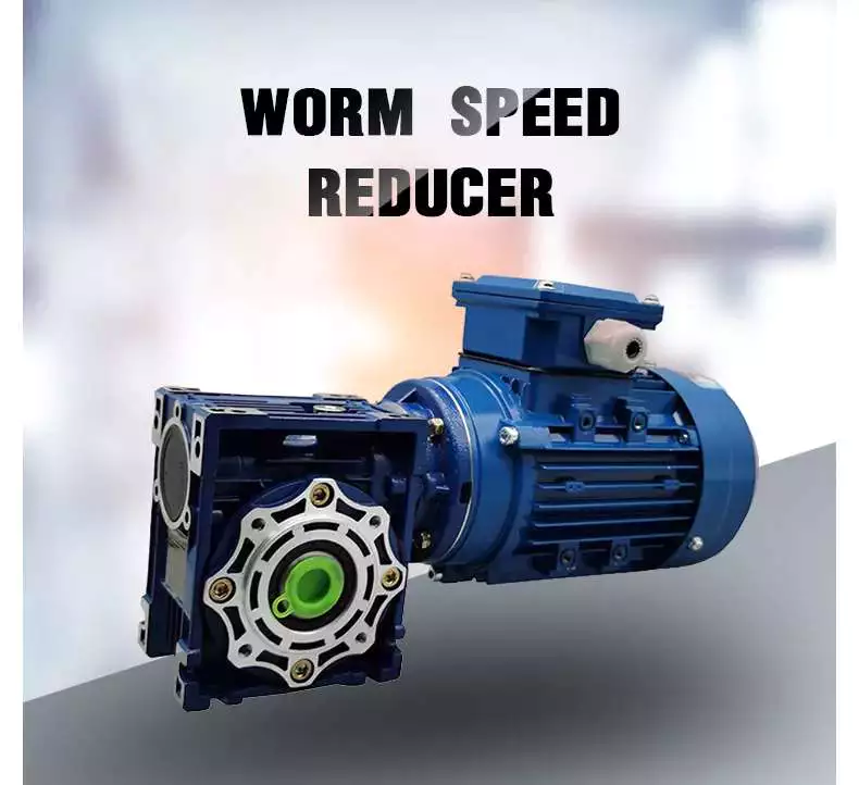
Features
Worm gears are popular in instruments that require fast stopping, such as elevators and lifts. Their soft materials allow them to absorb shock, which reduces the likelihood of failure. They are also beneficial in heavy-duty machines, such as rock crushers. Some manufacturers offer special worms with zero backlash and high-accuracy reduction.The worm reducer has a variety of features, including an axial pitch and a circular pitch. The axial pitch of the worm must match the circular pitch of the larger gear. Its threads are left or right-handed, and its lead angle is the distance a point on the thread travels during a revolution of the worm.The worm gear reducer is widely available, and gear manufacturers typically maintain a large inventory of them. Because worm gears are standardized, their mounting dimensions are generally uniform across manufacturers. This means that choosing one will not require you to change the height, length, or diameter of the output shaft. Worm gear reducers also have dimensional consistency.Worm gears are very efficient. They have a high load capacity and a low friction coefficient. The worm gears also have a precise tooth profile, which reduces speed fluctuations and allows for quiet operation.
Functions
Worm gears have different functions. They can be used in a variety of applications. For instance, they can be used in elevators to reduce the load on the elevator. These gears also have low noise levels because they are made of dissimilar metals. Moreover, these gears can be used in elevators because they are suitable for this type of application. However, they need a single stage reducer to function properly.Another important feature of a worm reducer is that it can operate in reverse. This means that the input shaft turns backwards, while the output shaft rotates forwards. Examples of such applications include hand-cranked centrifuges, blacksmithing forge blowers, and the wind governor of musical boxes. Worm gears are available in different shapes and sizes, from gearsets to housed units. They can also be configured as multi-speed designs. Some manufacturers also offer special precision and zero-backlash worms.A worm reducer’s tooth form is important in determining the capacity of the device. Typically, a single-lead worm gear has the same lead on the left and right tooth surfaces, although a dual-lead worm gear has different leads on each side. This feature helps to eliminate play in the worm gear. However, it is important to note that a worm reducer can be manufactured with different tooth shapes for different applications.The worm gear is an alternative to conventional gears. It operates in a similar fashion to ordinary gear drives. The main advantage of a worm gear is that it is able to reduce the rotational speed and torque of a rotating shaft. It also has the added benefit of being able to transfer motion at an angle of 90 degrees. The only drawback of a worm gear is that it cannot reverse motion.
Applications
This market report analyzes the Worm Reducer market from a global perspective. It includes a comprehensive analysis of the current market trends and future growth prospects. It also provides information about the competitive landscape and the main players in the industry. The report also highlights the key factors affecting the growth of the Worm Reducer market.
The major regional markets for the Worm Reducer include North America, Asia-Pacific, the Middle East and Africa, Latin America, and Europe. The market in these regions is likely to remain stable with a limited growth over the next few years. A worm gear is a small mechanical device that is connected to a larger gear. When connected together, it produces a low output speed but high torque.The gearing on a worm drive can be right-hand or left-hand, and can turn clockwise or counter-clockwise. Depending on the worm’s helix angles, back-driving and friction can be reduced. Worm gears are available in housed units or in gearsets. Some manufacturers offer integrated servomotors and multi-speed designs. High-accuracy and zero-backlash worms are available.Worm gears are particularly popular in instruments that require fast stops. They are also commonly found in elevators and lifts. Their soft nature and low-shock characteristics make them highly suitable for these types of machines.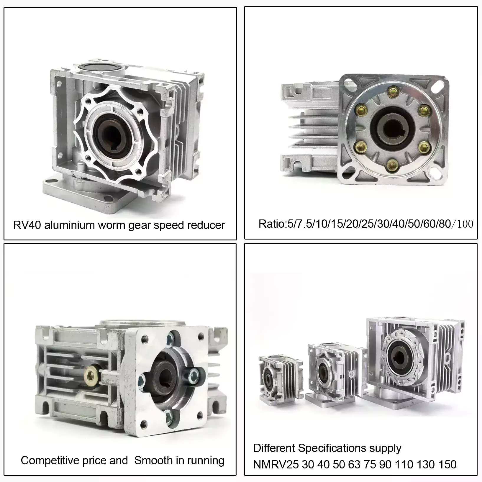
Cost
Cost is an important consideration when selecting a worm reducer. The initial cost of a worm gear reducer is considerably lower than other types of gear reducers. Worm gear reducers are also more energy-efficient, and have higher overload capacities than competitive systems. The following are factors that affect the cost of a worm gear reducer.Stainless steel worm gear reducers from WorldWide Electric offer great value for the money. They offer flange input and hollow output bore sizes, as well as center distances ranging from 1.75″ to 3.25″. In addition to the standard version, a stainless steel bushing kit is available, which allows users to use a wider range of head shaft sizes. Stainless steel worm gear reducers are available in stock from all six of WorldWide Electric’s regional warehouses. They also come with free prepaid freight.Worm gear reducers are often used in power transmission systems, elevators, conveyor belts, and medical equipment. In these applications, they are used to control the speed of a load and prevent it from freefall. While worm gear reducers are not as efficient as helical gearboxes, they are still very useful for applications that require high torque or high output rates.To select the right type of worm for your application, you should consider the number of teeth it contains. It’s best to select worms with a combined total of 40 teeth or more.
aspect
Worm reducers vary in size. They have one, two or more threads. Each thread has a lead angle. A high ratio has more teeth than a low gear, and a low ratio has fewer teeth. These differences are the result of gearing. The size of the worm gear reducer should be selected according to the specific application.The worm gear reducer saves space and provides more torque. Agknx Gearbox has created a variety of models to overcome common deceleration challenges, from standard to hygienic markets. The superior transmission Agknx range is designed to solve common deceleration challenges and expand to meet the needs of the sanitary industry.The diameter of the worm reducer is an important consideration. Its diameter should be equal to or slightly larger than the diameter of the grinding wheel or tool. This will affect the pressure angle. The pressure angle on a worm reducer depends on several factors, including its diameter and lead angle. The diameter of the grinding wheel or tool also has an effect on the profile of the worm.Worm gear reducers are common. Many gear manufacturers have large stocks of these gear reducers. Since gears are standardized, the mounting dimensions of worm gears are also common among manufacturers. This makes it easy to select a worm gear reducer for your application. In addition, the worm gear reducer is easy to install and maintain.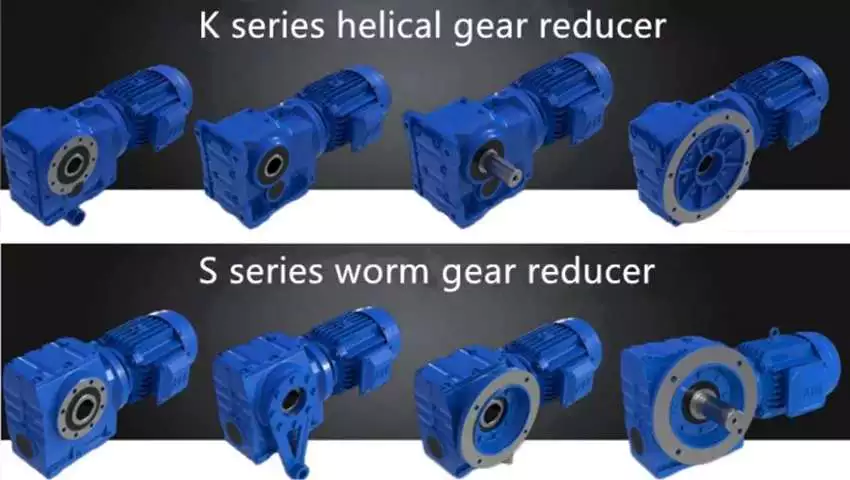
Worm gear reducer oil
Worm gear reducers usually use gear oil. Several types of gear oils are available, including synthetic, polyalkylene glycol, and mineral oils. The oil used in the worm gear reducer must have the right viscosity for the gear. Some oils are more corrosive than others and should be avoided if the environment is toxic.The oil of the worm gear reducer must be protected against corrosion, wear and friction. It is best to choose a lubricant with low friction rate, high oxidation resistance and good anti-wear protection. While mineral oils are the most common type of lubricant, synthetic base oils can improve gear efficiency and reduce operating temperatures. This is because the Arrhenius rate rule states that the chemical reaction in the oil doubles for every 10 degrees Celsius increase in temperature.Worm gear reducers are available in a variety of sizes and configurations. They are suitable for all kinds of machines and equipment. The sliding action between the worm gear and the output shaft produces high torque and high efficiency. If the transmission speed is low, the worm gear and output shaft can be combined for maximum efficiency.Worm gear reducers require less frequent oil changes than other types of gear reducers. However, regular oil should be changed every six months or 2,500 hours, whichever comes first. Also, it is a good idea to regularly monitor the oil level to prevent lubrication-related gearbox failures. It’s also wise to use synthetic oil, as it will last longer between oil changes.

