Product Description
Product Discription
Company Profile
HangZhou Terry Machinery Co.Ltd is a leading supplier of bearings, Linear motion system for CNC , Ball transfer Unit
and transmission component .the growing industrial and Favorable policy of HangZhou benefit the development of Terry
Machinery .Our products are utilized in industrial, motorcycle, vehicle and Automation applications. Now we are exporting
to 46 countries.including USA, GBR , Germany , Spain, Poland ,Turkey ect .The Goal of Terry Machinery to provide out
customers with widest range of products at competitive prices, backed with the best Service.OUR ADVANTAGE Products
Our major products & Supplied:Meet all the international standards and ISO9001 -TS1694 Certificate Big volume in Stock,
No MOQ required Personnel Our salespersons are well trained to accommodate your requests and speak English for your
conveniences.Our technicians and engineers Experience in the Industry area exceeds 23 years Service &Quality control ,
We supply detailed drawings and offer when ever necessary,We help all customers promote and improve their sales.We
inspect every piece of products by ourselves before delivery.
Customer Praise
FAQ
| Hardness: | Hardened Tooth Surface |
|---|---|
| Installation: | Flange |
| Gear Shape: | Cylindrical Gear |
| Gearing Arrangement: | Worm |
| Material of Housing: | Aluminum&Cast Iron |
| Color: | Blue Gray |
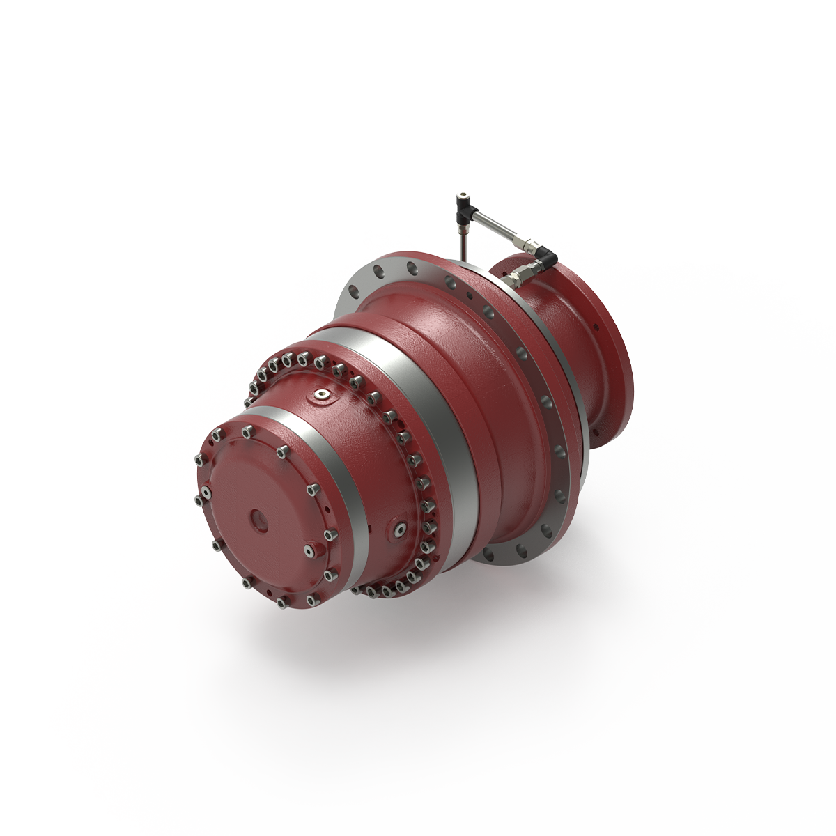
Can you provide insights into the importance of proper installation and alignment of winch drives?
Proper installation and alignment of winch drives are of utmost importance to ensure optimal performance, longevity, and safety of the system. Here’s a detailed explanation of the significance of proper installation and alignment of winch drives:
- Optimal Performance:
Proper installation and alignment are crucial for achieving optimal performance of winch drives. Precise alignment ensures that the winch drive operates within its designed parameters, minimizing power losses and maximizing efficiency. Accurate installation of components, such as motors, gearboxes, and brakes, ensures that they are properly integrated and aligned with each other. This alignment reduces mechanical stress, minimizes friction, and allows for smooth and reliable operation of the winch drive, resulting in improved performance and productivity.
- Extended Lifespan:
The correct installation and alignment of winch drives contribute to their longevity. When components are misaligned or improperly installed, it can lead to excessive wear, vibration, and premature failure of critical parts. Misalignment puts additional stress on bearings, shafts, gears, and other components, causing accelerated wear and reducing their lifespan. By ensuring proper alignment during installation, the load is distributed evenly, reducing mechanical stress and increasing the lifespan of the winch drive system.
- Reduced Maintenance and Downtime:
Proper installation and alignment can significantly reduce the need for maintenance and minimize downtime. Misalignment or improper installation can cause issues such as excessive heat generation, increased friction, and misoperation of safety mechanisms. These issues can lead to frequent breakdowns and unplanned downtime, resulting in productivity losses and increased maintenance costs. By ensuring correct alignment and installation, the risk of such issues is minimized, reducing the frequency of maintenance and improving overall system uptime.
- Enhanced Safety:
The safety of personnel and equipment is a critical consideration when it comes to winch drives. Improper installation and alignment can compromise the safety of the system. Misalignment can result in unexpected movements, excessive vibrations, or loss of control, posing risks to both operators and the surrounding environment. Proper alignment ensures that the winch drive operates within its intended parameters, reducing the likelihood of malfunctions, accidents, or equipment damage. It is essential to follow manufacturer guidelines and industry standards for installation and alignment to maintain a safe working environment.
- Efficient Power Transmission:
Correct alignment of winch drives ensures efficient power transmission from the motor to the drum or load. Misalignment can lead to power losses, increased energy consumption, and reduced overall system efficiency. Proper alignment ensures that the power is transmitted smoothly and efficiently, minimizing energy wastage and optimizing the performance of the winch drive. This not only improves energy efficiency but also reduces operating costs over the lifespan of the system.
In summary, the proper installation and alignment of winch drives are essential for achieving optimal performance, extending the lifespan of the system, reducing maintenance and downtime, enhancing safety, and ensuring efficient power transmission. Following manufacturer guidelines, industry standards, and engaging experienced professionals during installation and alignment processes is crucial to maximize the benefits and longevity of winch drive systems.

What safety considerations should be taken into account when using winch drives?
Using winch drives involves certain safety considerations to ensure the well-being of operators, prevent accidents, and protect the equipment and the load being lifted. Here’s a detailed explanation of the safety considerations that should be taken into account when using winch drives:
- Operator Training:
Proper training is essential for operators who will be using winch drives. They should receive comprehensive training on the safe operation of winch drives, including understanding the controls, procedures, safety features, and potential hazards. Training should cover load calculations, safe working loads, and the importance of following safety guidelines and manufacturer’s instructions.
- Equipment Inspection:
Prior to each use, winch drives should be thoroughly inspected to ensure they are in proper working condition. This includes checking for any signs of damage, wear, or corrosion. The cables or ropes should be inspected for fraying, kinks, or other defects. Any damaged or malfunctioning components should be repaired or replaced before operating the winch drive.
- Load Capacity:
It is crucial to adhere to the specified load capacity of the winch drive. Exceeding the maximum load capacity can lead to equipment failure, accidents, and injuries. Operators should accurately determine the weight of the load to be lifted and ensure it falls within the winch drive’s rated capacity. If the load exceeds the capacity, alternative lifting methods or equipment should be used.
- Secure Anchoring:
Winch drives should be securely anchored to a stable and appropriate mounting point. This ensures that the winch drive remains stable during operation and prevents unintended movement. The anchoring point should be capable of withstanding the forces generated during lifting or pulling operations. Proper anchoring minimizes the risk of equipment tipping over or shifting unexpectedly.
- Personal Protective Equipment (PPE):
Operators should wear appropriate personal protective equipment (PPE) when using winch drives. This may include safety helmets, gloves, eye protection, and high-visibility clothing. PPE helps protect operators from potential hazards such as falling objects, flying debris, or contact with moving parts. The specific PPE requirements should be determined based on the nature of the lifting operation and any applicable safety regulations.
- Safe Operating Distance:
Operators and other personnel should maintain a safe distance from the winch drive during operation. This prevents accidental contact with moving parts or the load being lifted. Clear warning signs or barriers should be used to define the restricted area around the winch drive. Operators should never place themselves or others in the potential path of the load or in a position where they could be struck by the load in case of a failure or slippage.
- Emergency Stop and Controls:
Winch drives should be equipped with emergency stop mechanisms or controls that allow operators to quickly halt the operation in case of an emergency. All operators should be familiar with the location and operation of the emergency stop controls. Regular testing and maintenance of these controls are essential to ensure their effectiveness in emergency situations.
- Proper Rigging and Rigging Techniques:
Correct rigging techniques should be followed when attaching the load to the winch drive. This includes using appropriate slings, hooks, or attachments and ensuring they are properly secured. Improper rigging can lead to load instability, shifting, or falling, posing a significant safety risk. Operators should be trained in proper rigging techniques and inspect the rigging components for wear or damage before each use.
- Regular Maintenance:
Winch drives should undergo regular maintenance as recommended by the manufacturer. This includes lubrication, inspection of cables or ropes, checking for loose bolts or connections, and verifying the functionality of safety features. Regular maintenance helps identify and address potential issues before they lead to equipment failure or accidents.
By considering these safety measures, operators can ensure the safe and effective use of winch drives, minimizing the risk of accidents, injuries, or equipment damage. It is crucial to prioritize safety at all times and to comply with applicable safety regulations and guidelines.
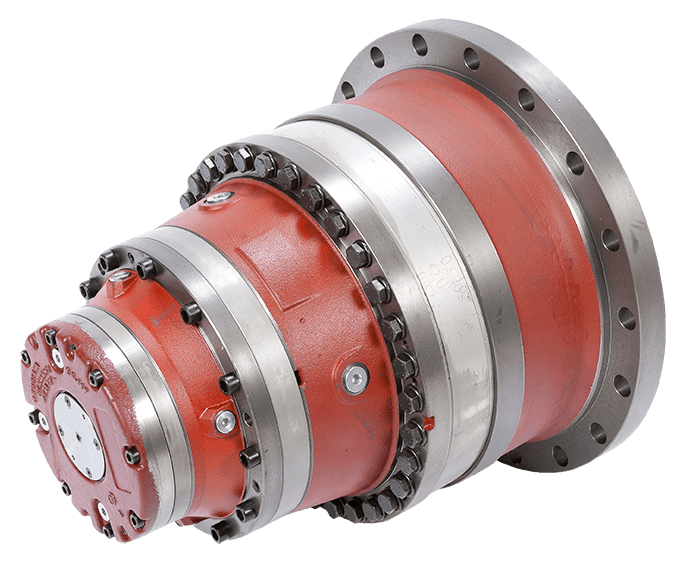
What are the advantages of using a winch drive in comparison to other lifting mechanisms?
Using a winch drive as a lifting mechanism offers several advantages over other lifting mechanisms. The unique characteristics and capabilities of winch drives make them a preferred choice in various applications. Here’s a detailed explanation of the advantages of using a winch drive in comparison to other lifting mechanisms:
- Versatility:
Winch drives offer versatility in terms of their application and adaptability to different industries. They can be utilized in a wide range of scenarios, including off-road recovery, marine operations, construction sites, and recreational activities. Winch drives can handle various load sizes and weights, making them suitable for both light and heavy lifting tasks. The ability to use winch drives in diverse environments and industries makes them a flexible and versatile choice for lifting and pulling operations.
- Control and Precision:
Winch drives provide precise control over the lifting and pulling operation. The gearing system allows operators to adjust the speed and direction of the winch drive, enabling accurate positioning and controlled movement of the load. This level of control is particularly beneficial in applications where precise load placement or delicate handling is required. Winch drives allow for fine adjustments and smooth operation, resulting in improved precision and reduced risk of damage to the load or surrounding structures.
- Pulling Power:
Winch drives are designed to generate significant pulling power, allowing them to handle heavy loads effectively. The power source, whether it’s an electric motor or hydraulic system, provides the necessary energy to generate substantial pulling force. This makes winch drives suitable for tasks that involve moving or lifting heavy objects, such as in construction, industrial settings, or vehicle recovery. The pulling power of winch drives gives them an advantage over other lifting mechanisms that may have limited capacity or require additional equipment for handling heavier loads.
- Compactness and Portability:
Winch drives are generally compact and portable, which enhances their usability in various settings. They can be easily mounted on vehicles, equipment, or structures, offering mobility and convenience. Compact winch drives are particularly useful in off-road vehicles, where space may be limited. The portability of winch drives allows for flexibility in different applications and enables their use in remote or challenging locations where other lifting mechanisms may not be easily accessible.
- Safety:
Winch drives are designed with safety features to ensure secure and controlled lifting operations. These features may include overload protection, emergency stop mechanisms, and limit switches. The braking system in winch drives provides reliable load holding, preventing unintentional load release. Additionally, winch drives can be equipped with remote control systems, allowing operators to maintain a safe distance during operation. The safety features and control mechanisms of winch drives contribute to enhanced safety and minimize the risk of accidents or injuries.
These advantages make winch drives a preferred choice over other lifting mechanisms in many applications. The versatility, control, pulling power, compactness, portability, and safety features of winch drives provide distinct benefits that cater to the specific requirements of lifting and pulling operations in various industries and scenarios.


editor by CX 2023-11-27
China high quality ND Ba801 Pto 540 Mini Aluminum Shell Bevel Gear Box for Agricultural Machinery worm gear reducer buy
Product Description
Product Description
|
Item No.: |
BA801, Cast Iron Housing Gearbox |
|
Ratio and Shaft: |
OEM acceptable |
|
Key word |
Agricultural Machinery Gearbox |
Company Profile
In 2571, HangZhou CZPT Machinery Co.,ltd was established by Ms. Iris and her 2 partners(Mr. Tian and Mr. Yang) in HangZhou city(ZHangZhoug province, China), all 3 Founders are engineers who have more than averaged 30 years of experience. Then becausethe requirements of business expansion, in 2014, it moved to the current Xihu (West Lake) Dis. Industrial Zone (HangZhou city, ZHangZhoug province, China).
Through our CZPT brand ND, CZPT Machinery delivers agricultural solutions to agriculture machinery manufacturer and distributors CZPT through a full line of spiral bevel gearboxes, straight bevel gearboxes, spur gearboxes, drive shafts,sheet metal, hydraulic cylinder, motors, tyre, worm gearboxes, worm operators etc. Products can be customized as request.
We, CZPT machinery established a complete quality management system and sales service network to provide clients with high-quality products and satisfactory service. Our products are sold in 40 provinces and municipalities in China and 36 countries and regions in the world, our main market is the European market.
Certifications
Packaging & Shipping
FAQ
Q: Are you a trading company or manufacturer?
A: We’re factory and providing gearbox ODM & OEM services for the European market for more than 10 years
Q: Do you provide samples? is it free or extra?
A: Yes, we could offer the sample for free charge but do not pay the cost of freight.
Q: How long is your delivery time? What is your terms of payment?
A: Generally it is 40-45 days. The time may vary depending on the product and the level of customization.
For standard products, the payment is: 30% T/T in advance,balance before shipment.
Q: What is the exact MOQ or price for your product?
A: As an OEM company, we can provide and adapt our products to a wide range of needs.
Thus, MOQ and price may greatly vary with size, material and further specifications; For instance, costly products or standard products will usually have a lower MOQ. Please contact us with all relevant details to get the most accurate quotation.
If you have another question, please feel free to contact us.
| Application: | Machinery, Agricultural Machinery |
|---|---|
| Function: | Distribution Power, Change Drive Torque, Change Drive Direction, Speed Changing, Speed Reduction, Speed Increase |
| Layout: | Straight or Spiral Bevel Gear |
| Hardness: | Hardened Tooth Surface |
| Installation: | Vertical Type |
| Step: | Single-Step |
| Customization: |
Available
|
|
|---|
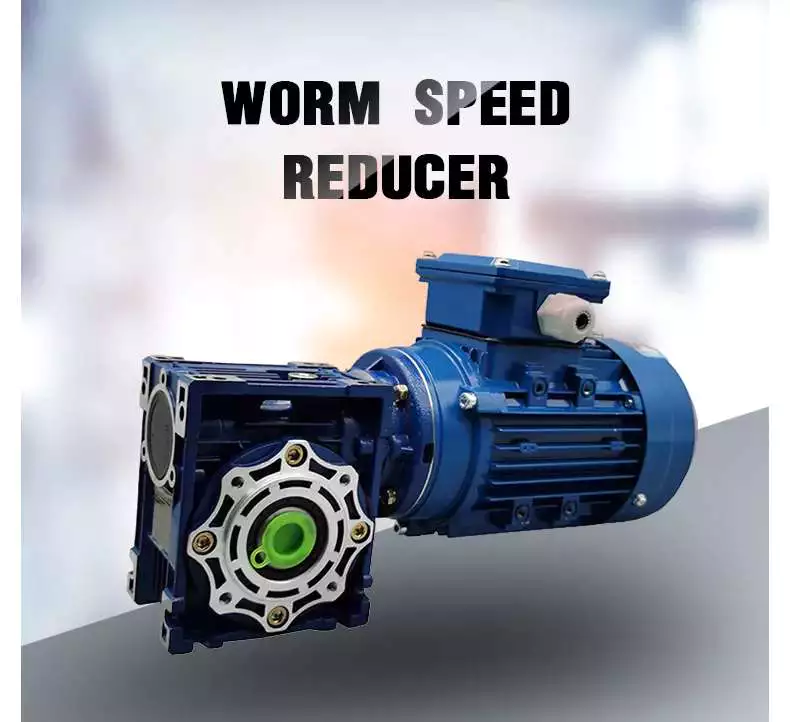
What is a worm gear reducer gearbox?
A worm gear reducer gearbox is a mechanical device that uses a worm gear and a worm to reduce the speed of a rotating shaft. The gear reducer gearbox can increase the output torque of the engine according to the gear ratio. This type of gear reducer gearbox is characterized by its flexibility and compact size. It also increases the strength and efficiency of the drive.
Hollow shaft worm gear reducer gearbox
The hollow shaft worm gear reducer gearbox is an additional output shaft connecting various motors and other gearboxes. They can be installed horizontally or vertically. Depending on size and scale, they can be used with gearboxes from 4GN to 5GX.
Worm gear reducer gearboxes are usually used in combination with helical gear reducer gearboxes. The latter is mounted on the input side of the worm gear reducer gearbox and is a great way to reduce the speed of high output motors. The gear reducer gearbox has high efficiency, low speed operation, low noise, low vibration and low energy consumption.
Worm gear reducer gearboxes are made of hard steel or non-ferrous metals, increasing their efficiency. However, gears are not indestructible, and failure to keep running can cause the gear oil to rust or emulsify. This is due to moisture condensation that occurs during the operation and shutdown of the reducer gearbox. The assembly process and quality of the bearing are important factors to prevent condensation.
Hollow shaft worm gear reducer gearboxes can be used in a variety of applications. They are commonly used in machine tools, variable speed drives and automotive applications. However, they are not suitable for continuous operation. If you plan to use a hollow shaft worm gear reducer gearbox, be sure to choose the correct one according to your requirements.
Double throat worm gear
Worm gear reducer gearboxes use a worm gear as the input gear. An electric motor or sprocket drives the worm, which is supported by anti-friction roller bearings. Worm gears are prone to wear due to the high friction in the gear teeth. This leads to corrosion of the confinement surfaces of the gears.
The pitch diameter and working depth of the worm gear are important. The pitch circle diameter is the diameter of the imaginary circle in which the worm and the gear mesh. Working depth is the maximum amount of worm thread that extends into the backlash. Throat diameter is the diameter of the circle at the lowest point of the worm gear face.
When the friction angle between the worm and the gear exceeds the lead angle of the worm, the worm gear is self-locking. This feature is useful for lifting equipment, but may be detrimental to systems that require reverse sensitivity. In these systems, the self-locking ability of the gears is a key limitation.
The double throat worm gear provides the tightest connection between the worm and the gear. The worm gear must be installed correctly to ensure maximum efficiency. One way to install the worm gear assembly is through a keyway. The keyway prevents the shaft from rotating, which is critical for transmitting torque. Then attach the gear to the hub using the set screw.
The axial and circumferential pitch of the worm gear should match the pitch diameter of the larger gear. Single-throat worm gears are single-threaded, and double-throat worm gears are double-throat. A single thread design advances one tooth, while a double thread design advances two teeth. The number of threads should match the number of mating gears.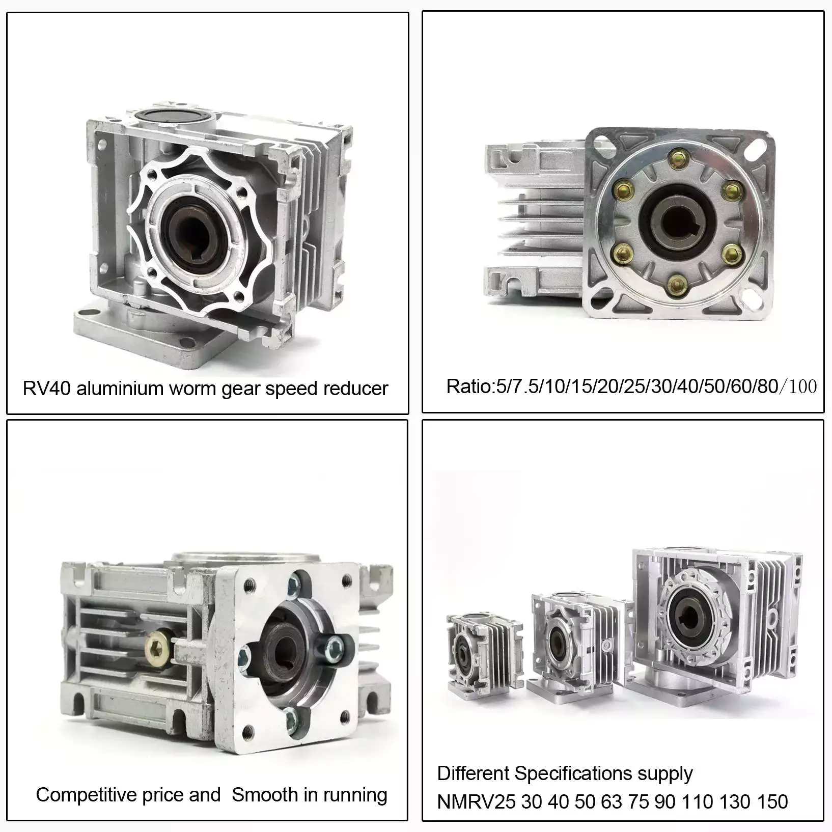
Self-locking function
One of the most prominent features of a worm reducer gearbox is its self-locking function, which prevents the input and output shafts from being interchanged. The self-locking function is ideal for industrial applications where large gear reduction ratios are required without enlarging the gear box.
The self-locking function of a worm reducer gearbox can be achieved by choosing the right type of worm gear. However, it should be noted that this feature is not available in all types of worm gear reducer gearboxes. Worm gears are self-locking only when a specific speed ratio is reached. When the speed ratio is too small, the self-locking function will not work effectively.
Self-locking status of a worm reducer gearbox is determined by the lead, pressure, and coefficient of friction. In the early twentieth century, cars had a tendency to pull the steering toward the side with a flat tire. A worm drive reduced this tendency by reducing frictional forces and transmitting steering force to the wheel, which aids in steering and reduces wear and tear.
A self-locking worm reducer gearbox is a simple-machine with low mechanical efficiency. It is self-locking when the work at one end is greater than the work at the other. If the mechanical efficiency of a worm reducer gearbox is less than 50%, the friction will result in losses. In addition, the self-locking function is not applicable when the drive is reversed. This characteristic makes self-locking worm gears ideal for hoisting and lowering applications.
Another feature of a worm reducer gearbox is its ability to reduce axially. Worm gears can be double-lead or single-lead, and it is possible to adjust their backlash to compensate for tooth wear.
Heat generated by worm gears
Worm gears generate considerable amounts of heat. It is essential to reduce this heat to improve the performance of the gears. This heat can be mitigated by designing the worms with smoother surfaces. In general, the speed at which worm gears mesh should be in the range of 20 to 24 rms.
There are many approaches for calculating worm gear efficiency. However, no other approach uses an automatic approach to building the thermal network. The other methods either abstractly investigate the gearbox as an isothermal system or build the TNM statically. This paper describes a new method for automatically calculating heat balance and efficiency for worm gears.
Heat generated by worm gears is a significant source of power loss. Worm gears are typically characterized by high sliding speeds in their tooth contacts, which causes high frictional heat and increased thermal stresses. As a result, accurate calculations are necessary to ensure optimal operation. In order to determine the efficiency of a gearbox system, manufacturers often use the simulation program WTplus to calculate heat loss and efficiency. The heat balance calculation is achieved by adding the no-load and load-dependent power losses of the gearbox.
Worm gears require a special type of lubricant. A synthetic oil that is non-magnetic and has a low friction coefficient is used. However, the oil is only one of the options for lubricating worm gears. In order to extend the life of worm gears, you should also consider adding a natural additive to the lubricant.
Worm gears can have a very high reduction ratio. They can achieve massive reductions with little effort, compared to conventional gearsets which require multiple reductions. Worm gears also have fewer moving parts and places for failure than conventional gears. One disadvantage of worm gears is that they are not reversible, which limits their efficiency.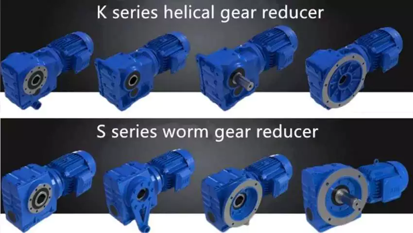
Size of worm gear reducer gearbox
Worm gear reducer gearboxes can be used to decrease the speed of a rotating shaft. They are usually designed with two shafts at right angles. The worm wheel acts as both the pinion and rack. The central cross section forms the boundary between the advancing and receding sides of the worm gear.
The output gear of a worm gear reducer gearbox has a small diameter compared to the input gear. This allows for low-speed operation while producing a high-torque output. This makes worm gear reducer gearboxes great for space-saving applications. They also have low initial costs.
Worm gear reducer gearboxes are one of the most popular types of speed reducer gearboxes. They can be small and powerful and are often used in power transmission systems. These units can be used in elevators, conveyor belts, security gates, and medical equipment. Worm gearing is often found in small and large sized machines.
Worm gears can also be adjusted. A dual-lead worm gear has a different lead on the left and right tooth surfaces. This allows for axial movement of the worm and can also be adjusted to reduce backlash. A backlash adjustment may be necessary as the worm wears down. In some cases, this backlash can be adjusted by adjusting the center distance between the worm gear.
The size of worm gear reducer gearbox depends on its function. For example, if the worm gear is used to reduce the speed of an automobile, it should be a model that can be installed in a small car.


editor by CX 2023-06-06