Product Description
Product Advantages
| Size | R37 | R57 | R77 | R87 | R107 |
| Ratio | 3.41-134.82 | 4.39-782 | 5.31-1430 | 5.3-2873 | 6.66-7583 |
| Power | 0.12KW-3KW | 0.12KW-7.5KW | 0.12KW-11KW | 0.12KW-18.5KW | 0.12KW-18.5KW |
| Output torque | 30-205N.M | 40-400N.M | 50-795N.M | 50-1610N.M | 80-4870N.M |
| Output speed(RPM) | 0.1-821RPM | 0.1-660RPM | 0.1-795RPM | 0.1-276RPM | 0.1-220RPM |
R series reducer has the characteristics of small volume and large torque transmission. It is designed and manufactured on the basis of modular combination system. There are many motor combinations,installation forms and structural schemes. R series reducer adopts the modular design principle of unit structure, with high transmission efficiency, low energy consumption and superior performance.
Product Description
Detailed Photos
Our Advantages
/* January 22, 2571 19:08:37 */!function(){function s(e,r){var a,o={};try{e&&e.split(“,”).forEach(function(e,t){e&&(a=e.match(/(.*?):(.*)$/))&&1
| Application: | Motor, Motorcycle, Machinery, Agricultural Machine, Lift |
|---|---|
| Hardness: | Hardened Tooth Surface |
| Installation: | Horizontal Type |
| Layout: | Expansion, Parallel |
| Gear Shape: | Bevel Gear |
| Step: | Single-Step |
| Samples: |
US$ 500/Piece
1 Piece(Min.Order) | |
|---|
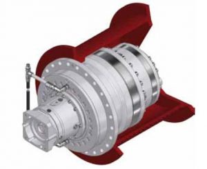
How do electronic or computer-controlled components integrate with winch drives in modern applications?
In modern applications, electronic or computer-controlled components play a crucial role in enhancing the functionality, precision, and safety of winch drives. These components integrate with winch drives to provide advanced control, monitoring, and automation capabilities. Here’s a detailed explanation of how electronic or computer-controlled components integrate with winch drives in modern applications:
- Control Systems:
Electronic or computer-controlled components are used to create sophisticated control systems for winch drives. These control systems allow operators to precisely control the speed, direction, and position of the winch drive. By integrating sensors, actuators, and feedback mechanisms, the control system can monitor the operating conditions and adjust parameters in real-time to optimize performance. Control systems may include programmable logic controllers (PLCs), microcontrollers, or dedicated electronic control units (ECUs) that communicate with the winch drive to execute commands and maintain desired operating parameters.
- Human-Machine Interfaces (HMIs):
Electronic components enable the integration of intuitive and user-friendly Human-Machine Interfaces (HMIs) with winch drives. HMIs provide a visual interface for operators to interact with the winch drive system. Touchscreen displays, buttons, switches, and graphical user interfaces (GUIs) allow operators to input commands, monitor system status, and access diagnostic information. HMIs also facilitate the adjustment of control parameters, alarm settings, and operational modes. The integration of HMIs enhances operator control and simplifies the operation of winch drives in modern applications.
- Sensors and Feedback Systems:
Electronic sensors are employed to gather real-time data about various parameters related to the winch drive and the operating environment. These sensors can measure variables such as load weight, cable tension, speed, temperature, and motor current. The collected data is then fed back to the control system, allowing it to make informed decisions and adjustments. For example, if the load exceeds a predefined limit, the control system can send a signal to stop the winch drive or activate an alarm. Sensors and feedback systems ensure accurate monitoring of operating conditions and enable proactive control and safety measures.
- Communication Protocols:
Electronic or computer-controlled components facilitate communication between winch drives and other devices or systems. Modern winch drives often support various communication protocols, such as Ethernet, CAN bus, Modbus, or Profibus, which enable seamless integration with higher-level control systems, supervisory systems, or industrial networks. This integration allows for centralized control, remote monitoring, and data exchange between the winch drive and other components or systems, enhancing coordination and automation in complex applications.
- Automation and Programmability:
Electronic or computer-controlled components enable advanced automation and programmability features in winch drives. With the integration of programmable logic controllers (PLCs) or microcontrollers, winch drives can execute pre-programmed sequences of operations, follow specific load profiles, or respond to external commands and triggers. Automation reduces manual intervention, improves efficiency, and enables synchronized operation with other equipment or systems. Programmability allows customization and adaptation of winch drive behavior to meet specific application requirements.
- Diagnostics and Condition Monitoring:
Electronic components enable comprehensive diagnostics and condition monitoring of winch drives. Built-in sensors, data logging capabilities, and advanced algorithms can monitor the health, performance, and operating parameters of the winch drive in real-time. This information can be used for predictive maintenance, early fault detection, and performance optimization. Additionally, remote access and network connectivity enable remote monitoring and troubleshooting, reducing downtime and improving maintenance efficiency.
In summary, electronic or computer-controlled components integrate with winch drives in modern applications to provide advanced control, monitoring, automation, and safety features. These components enable precise control, user-friendly interfaces, data-driven decision-making, communication with other systems, automation, and diagnostics. The integration of electronic components enhances the functionality, efficiency, and reliability of winch drives in a wide range of applications.
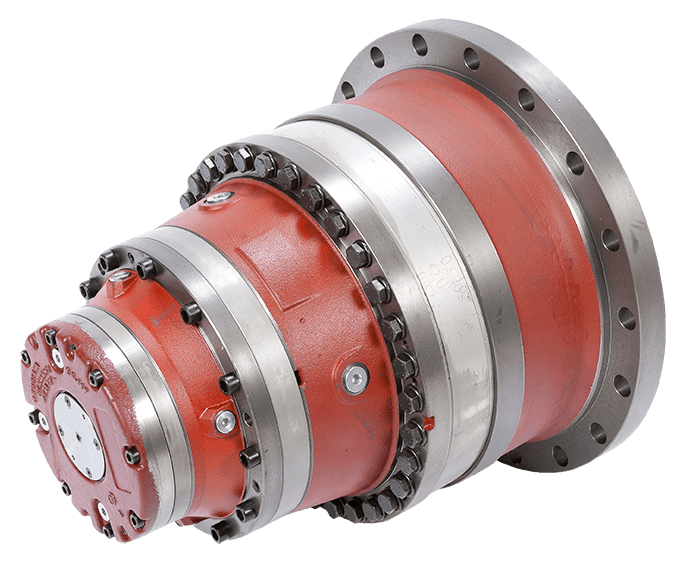
How does the design of winch drives impact their performance in different environments?
The design of winch drives plays a critical role in determining their performance in different environments. Various design factors influence the reliability, efficiency, and adaptability of winch drives to specific operating conditions. Here’s a detailed explanation of how the design of winch drives impacts their performance:
- Load Capacity and Power:
The design of winch drives directly affects their load capacity and power capabilities. Factors such as motor size, gear ratio, and drum diameter determine the maximum load capacity a winch drive can handle. The power output of the motor and the mechanical advantage provided by the gear system impact the winch drive’s ability to lift or pull heavy loads effectively. A well-designed winch drive with appropriate load capacity and power ensures optimal performance in different environments.
- Speed and Control:
The design of winch drives influences their speed and control characteristics. The gear ratio and motor specifications determine the speed at which the winch drive can operate. Additionally, the presence of a variable speed control mechanism allows for precise and controlled movement of loads. The design should strike a balance between speed and control, depending on the specific application and operational requirements in different environments.
- Drive System:
Winch drives can utilize different drive systems, such as electric, hydraulic, or pneumatic. The design of the drive system impacts the performance of the winch drive in different environments. Electric winch drives are commonly used due to their ease of use, precise control, and suitability for various applications. Hydraulic winch drives offer high power output and are often preferred in heavy-duty applications. Pneumatic winch drives are suitable for environments where electricity or hydraulics are not readily available. The design should align with the specific requirements and constraints of the environment in which the winch drive will be used.
- Enclosure and Protection:
The design of the winch drive enclosure and protection features significantly impacts its performance in different environments. Winch drives used in outdoor or harsh environments should have robust enclosures that provide protection against dust, moisture, and other contaminants. Sealed or weatherproof enclosures prevent damage to internal components and ensure reliable operation. Additionally, features such as thermal protection and overload protection are designed to safeguard the winch drive from overheating or excessive strain, enhancing its performance and longevity.
- Mounting and Installation:
The design of winch drives should consider the ease of mounting and installation. Mounting options such as bolt-on, weld-on, or integrated mounting plates offer flexibility for different installation scenarios. The design should also take into account the space constraints and mounting requirements of the specific environment. Easy and secure installation ensures proper alignment, stability, and efficient operation of the winch drive.
- Control and Safety Features:
The design of winch drives includes control and safety features that impact their performance in different environments. Control systems can range from simple push-button controls to advanced remote controls or integrated control panels. The design should provide intuitive and user-friendly control interfaces for efficient operation. Safety features such as emergency stop mechanisms, load limiters, and overload protection are crucial to prevent accidents and ensure safe operation in various environments. The design should prioritize the incorporation of appropriate safety features based on the specific application and environmental conditions.
By considering these design factors, winch drives can be optimized for performance, reliability, and safety in different environments. A well-designed winch drive that aligns with the specific requirements of the environment will deliver efficient and effective lifting or pulling capabilities while ensuring long-term durability and functionality.

What is a winch drive, and how is it utilized in various applications?
A winch drive is a mechanical system designed to provide controlled pulling or lifting capabilities using a spool or drum around which a cable or rope is wound. It consists of a power source, such as an electric motor or hydraulic system, coupled with a gearbox or transmission mechanism to control the speed and torque output. Winch drives are widely utilized in various applications that require the controlled movement of heavy loads. Here’s a detailed explanation of winch drives and their utilization in different applications:
- Off-Road Vehicles and Recovery:
Winch drives are commonly used in off-road vehicles, such as trucks, SUVs, and ATVs, for recovery purposes. In situations where a vehicle gets stuck or needs to be pulled out of challenging terrain, a winch drive mounted on the vehicle’s front or rear bumper can be employed. The winch drive’s cable is connected to a secure anchor point, and as the winch motor rotates, it winds the cable onto the drum, exerting a pulling force that helps extract the vehicle from the obstacle. Winch drives provide reliable pulling power and are essential for off-road enthusiasts, emergency services, and military applications.
- Marine and Boating:
In marine and boating applications, winch drives are utilized for various tasks, including anchoring, mooring, and lifting heavy loads. Winches are commonly found on sailboats and powerboats to control the sails, raise and lower the anchor, or assist in docking. They are also used in larger vessels and ships for cargo handling, launching and recovering small boats or life rafts, and handling equipment on deck. The versatility and strength of winch drives make them indispensable in the maritime industry, providing precise and controlled pulling or lifting capabilities in demanding marine environments.
- Construction and Industrial:
Winch drives play a vital role in construction and industrial settings, where the controlled movement of heavy materials and equipment is required. They are utilized in cranes, hoists, and lifting systems to perform tasks such as raising and lowering loads, positioning materials, and erecting structures. Winches can also be found in material handling equipment, such as forklifts and telehandlers, to assist in loading and unloading operations. In construction sites, winch drives are valuable for activities like tensioning cables, pulling machinery, and operating temporary lifts. The robustness and reliability of winch drives make them essential tools in the construction and industrial sectors.
- Recreational and Entertainment:
Winch drives are utilized in various recreational and entertainment applications. In amusement parks and adventure facilities, winches are often used in zip line systems, allowing participants to traverse from one point to another safely. They are also employed in aerial lifts and chairlifts for ski resorts and mountainous areas. Winches provide controlled and reliable movement, ensuring the safety and enjoyment of individuals engaging in recreational activities. Additionally, winches are utilized in stage productions and theatrical settings to create dynamic effects, such as flying performers or moving set pieces.
- Automotive and Garage:
In automotive and garage settings, winch drives find utility in a variety of applications. They are commonly used in car haulers and trailers to load and unload vehicles onto the platform. Winches are also employed in automotive repair and maintenance, assisting in tasks such as engine removal, vehicle recovery, and frame straightening. In home garages, winch drives can be utilized for lifting heavy objects, such as engines or equipment. The versatility and compactness of winch drives make them valuable tools for automotive enthusiasts, professional mechanics, and DIY enthusiasts.
In summary, a winch drive is a mechanical system that provides controlled pulling or lifting capabilities using a spool or drum and a power source. They are employed in various applications, including off-road vehicle recovery, marine and boating operations, construction and industrial tasks, recreational and entertainment activities, automotive and garage settings. Winch drives offer reliable and controlled movement, allowing for the handling of heavy loads in a wide range of settings and industries.


editor by CX 2024-04-04
China wholesaler CZPT Factory Price 1-Stage Ratio 5: 1 Spur Gear Planetary Reducer Gearbox worm gearbox application
Product Description
Factory Price 1-Stage Ratio 5:1 Spur Gear Planetary Reducer Gearbox
Planetary gearbox is a kind of reducer with wide versatility. The inner gear adopts low carbon alloy steel carburizing quenching and grinding or nitriding process. Planetary gearbox has the characteristics of small structure size, large output torque, high speed ratio, high efficiency, safe and reliable performance, etc. The inner gear of the planetary gearbox can be divided into spur gear and helical gear. Customers can choose the right precision reducer according to the needs of the application.
Product Description
Description:
1.The output shaft is made of large size,large span double bearing design,output shaft and planetary arm bracket as a whole.The input shaft is placed directly on the planet arm bracket to ensure that the reducer has high operating accuracy and maximum torsional rigidity.
2.Shell and the inner ring gear used integrated design,quenching and tempering after the processing of the teeth so that it can achieve high torque,high precision,high wear resistance.Moreover surface nickel-plated anti-rust treatment,so that its corrosion resistance greatly enhanced.
3.The planetary gear transmission employs full needle roller without retainer to increase the contact surface,which greatly upgrades structural rigidity and service life.
4.The gear is made of Japanese imported material.After the metal cutting process,the vacuum carburizing heat treatment to 58-62HRC. And then by the hobbing,Get the best tooth shape,tooth direction,to ensure that the gear of high precision and good impact toughness.
5.Input shaft and sun gear integrated structure,in order to improve the operation accuracy of the reducer.
6.Ring gear processing technology: Using internal gear slotting machine and hobbing machine; the precision of ring gear after processing can reach .GB7.
Planetary reducer characteristic:
1.With bevel gear reversing mechanism,right angle steering output is realized;
2.Square flange output,standard size;
3.The input specification are complete and there are many choices;
4.Spur transmission ,single cantilever structurer,design simple,high cost performance;
5.Keyway can be opened in the force shaft;
6.stable operation,low noise;
7.Size range:60-120mm
8.Ratio range:3-100;
9.Backlash:8-16arcmin;
10.Support custom according to drawings or samples
| Specifications | PVFN60 | PVFN90 | PVFN120 | |||
| Technal Parameters | ||||||
| Max. Torque | Nm | 1.5times rated torque | ||||
| Emergency Stop Torque | Nm | 2.5times rated torque | ||||
| Max. Radial Load | N | 240 | 450 | 1240 | ||
| Max. Axial Load | N | 220 | 430 | 1000 | ||
| Torsional Rigidity | Nm/arcmin | 1.8 | 4.85 | 11 | ||
| Max.Input Speed | rpm | 8000 | 6000 | 6000 | ||
| Rated Input Speed | rpm | 4000 | 3500 | 3500 | ||
| Noise | dB | ≤58 | ≤60 | ≤65 | ||
| Average Life Time | h | 20000 | ||||
| Efficiency Of Full Load | % | L1≥95% L2≥92% | ||||
| Return Backlash | P1 | L1 | arcmin | ≤8 | ≤8 | ≤8 |
| L2 | arcmin | ≤12 | ≤12 | ≤12 | ||
| P2 | L1 | arcmin | ≤16 | ≤16 | ≤16 | |
| L2 | arcmin | ≤20 | ≤20 | ≤20 | ||
| Moment Of Inertia Table | L1 | 3 | Kg*cm2 | 0.46 | 1.73 | 12.78 |
| 4 | Kg*cm2 | 0.46 | 1.73 | 12.78 | ||
| 5 | Kg*cm2 | 0.46 | 1.73 | 12.78 | ||
| 7 | Kg*cm2 | 0.41 | 1.42 | 11.38 | ||
| 10 | Kg*cm2 | 0.41 | 1.42 | 11.38 | ||
| L2 | 12 | Kg*cm2 | 0.44 | 1.49 | 12.18 | |
| 15 | Kg*cm2 | 0.44 | 1.49 | 12.18 | ||
| 16 | Kg*cm2 | 0.72 | 1.49 | 12.18 | ||
| 20 | Kg*cm2 | 0.44 | 1.49 | 12.18 | ||
| 25 | Kg*cm2 | 0.44 | 1.49 | 12.18 | ||
| 28 | Kg*cm2 | 0.44 | 1.49 | 12.18 | ||
| 30 | Kg*cm2 | 0.44 | 1.49 | 12.18 | ||
| 35 | Kg*cm2 | 0.44 | 1.49 | 12.18 | ||
| 40 | Kg*cm2 | 0.44 | 1.49 | 12.18 | ||
| 50 | Kg*cm2 | 0.34 | 1.25 | 11.48 | ||
| 70 | Kg*cm2 | 0.34 | 1.25 | 11.48 | ||
| 100 | Kg*cm2 | 0.34 | 1.25 | 11.48 | ||
| Technical Parameter | Level | Ratio | PVFN60 | PVFN90 | PVFN120 | |
| Rated Torque | L1 | 3 | Nm | 27 | 96 | 161 |
| 4 | Nm | 40 | 122 | 210 | ||
| 5 | Nm | 40 | 122 | 210 | ||
| 7 | Nm | 34 | 95 | 170 | ||
| 10 | Nm | 16 | 56 | 86 | ||
| L2 | 12 | Nm | 27 | 96 | 161 | |
| 15 | Nm | 27 | 96 | 161 | ||
| 16 | Nm | 40 | 122 | 210 | ||
| 20 | Nm | 40 | 122 | 210 | ||
| 25 | Nm | 40 | 122 | 210 | ||
| 28 | Nm | 40 | 122 | 210 | ||
| 30 | Nm | 27 | 96 | 161 | ||
| 35 | Nm | 40 | 122 | 210 | ||
| 40 | Nm | 40 | 122 | 210 | ||
| 50 | Nm | 40 | 122 | 210 | ||
| 70 | Nm | 34 | 95 | 170 | ||
| 100 | Nm | 16 | 56 | 86 | ||
| Degree Of Protection | IP65 | |||||
| Operation Temprature | ºC | – 10ºC to -90ºC | ||||
| Weight | L1 | kg | 1.7 | 4.4 | 12 | |
| L2 | kg | 1.9 | 5 | 14 | ||
Company Profile
Packaging & Shipping
1. Lead time: 7-10 working days as usual, 20 working days in busy season, it will be based on the detailed order quantity;
2. Delivery: DHL/ UPS/ FEDEX/ EMS/ TNT
FAQ
1. who are we?
Hefa Group is based in ZheJiang , China, start from 1998,has a 3 subsidiaries in total.The Main Products is planetary gearbox,timing belt pulley, helical gear,spur gear,gear rack,gear ring,chain wheel,hollow rotating platform,module,etc
2. how can we guarantee quality?
Always a pre-production sample before mass production;
Always final Inspection before shipment;
3. how to choose the suitable planetary gearbox?
First of all,we need you to be able to provide relevant parameters.If you have a motor drawing,it will let us recommend a suitable gearbox for you faster.If not,we hope you can provide the following motor parameters:output speed,output torque,voltage,current,ip,noise,operating conditions,motor size and power,etc
4. why should you buy from us not from other suppliers?
We are 22 years experiences manufacturer on making the gears, specializing in manufacturing all kinds of spur/bevel/helical gear, grinding gear, gear shaft, timing pulley, rack, planetary gear reducer, timing belt and such transmission gear parts
5. what services can we provide?
Accepted Delivery Terms: Fedex,DHL,UPS;
Accepted Payment Currency:USD,EUR,HKD,GBP,CNY;
Accepted Payment Type: T/T,L/C,PayPal,Western Union;
Language Spoken:English,Chinese,Japanese
| Application: | Motor, Motorcycle, Machinery, Marine, Agricultural Machinery, Manipulator |
|---|---|
| Function: | Change Drive Torque, Change Drive Direction, Speed Reduction |
| Layout: | Coaxial |
| Hardness: | Hardened Tooth Surface |
| Installation: | Vertical Type |
| Step: | Single-Step |
| Samples: |
US$ 288/Piece
1 Piece(Min.Order) | |
|---|
| Customization: |
Available
|
|
|---|
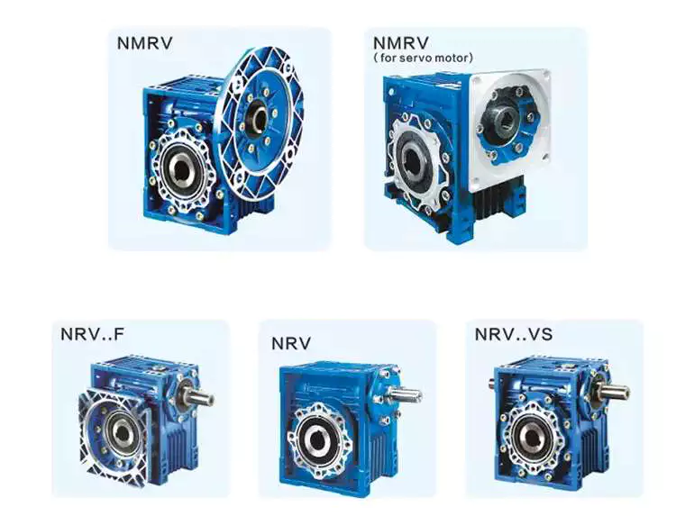
Worm gear reducer gearbox
A worm gear reducer gearbox is a gear reducer gearbox that uses a worm gear train to reduce the required force. Unlike traditional gear reducer gearboxes, these units are small and require low horsepower ratings. This reduces their efficiency, but their low cost and compact design help make up for this shortcoming. However, these gear reducer gearboxes have some drawbacks, including their tendency to lock up when reversing.
high efficiency
High-efficiency worm reducer gearboxes are ideal for applications where high performance, repeatability, and accuracy are critical. It consists of an input hypoid gear and an output hypoid bevel gear. The input worm rotates perpendicular to the output worm, so for every revolution of the input worm, the output gear makes one revolution. This arrangement reduces friction (another source of energy loss) in a high-efficiency worm gear to at least two arc minutes.
Compared with worm gear reducer gearboxes, hypoid gearmotors offer several advantages, including lower operating costs and higher efficiency. For example, hypoid gear motors can transmit more torque even at high reduction ratios. Also, they are more efficient than worm gear reducer gearboxes, which means they can produce the same output with a smaller motor.
In recent years, the efficiency of worm gear reducer gearboxes has been dramatically improved. Manufacturers have made great strides in materials, design, and manufacturing. New designs, including dual-enveloping worm gear reducer gearboxes, increase efficiency by 3 to 8 percent. These improvements were made possible through countless hours of testing and development. Worm gear reducer gearboxes also offer lower initial costs and higher overload capability than competing systems.
Worm gear reducer gearboxes are popular because they provide maximum reduction in a small package. Their compact size makes them ideal for low to medium-horsepower applications and they are reticent. They also offer higher torque output and better shock load tolerance. Finally, they are an economical option to reduce the device’s power requirements.
low noise
Low-noise worm gear reducer gearboxes are designed to reduce noise in industrial applications. This type of reducer gearbox uses fewer bearings and can work in various mounting positions. Typically, a worm reducer gearbox is a single-stage unit with only one shaft and one gear. Since there is only one gear, the noise level of the worm gear reducer gearbox will be lower than other types.
A worm gear reducer gearbox can be integrated into the electric power steering system to reduce noise. Worm reducer gearboxes can be made and from many different materials. The following three-stage process will explain the components of a low-noise worm reducer gearbox.
Worm gear reducer gearboxes can be mounted at a 90-degree angle to the input worm shaft and are available with various types of hollow or solid output shafts. These reducer gearboxes are especially beneficial for applications where noise reduction is essential. They also have fewer parts and are smaller than other types of reducer gearboxes, making them easier to install.
Worm gear reducer gearboxes are available from various manufacturers. Due to their widespread availability, gear manufacturers maintain extensive inventories of these reducer gearboxes. The worm gear ratio is standard, and the size of the worm gear reducer gearbox is universal. Also, worm gear reducer gearboxes do not need to be sized for a specific purpose, unlike other load interruptions.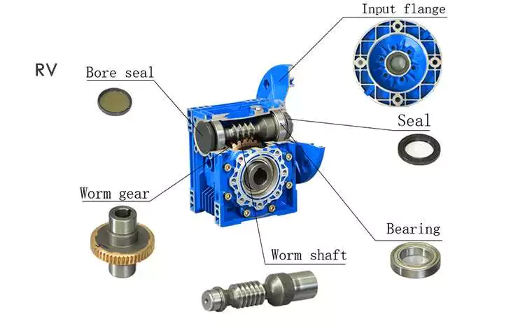
A worm gear reducer gearbox is a transmission mechanism with a compact structure, large transmission ratio, and self-locking function under certain conditions. The worm gear reducer gearbox series products are designed with American technology and have the characteristics of stable transmission, strong bearing capacity, low noise, and compact structure. In addition, these products can provide a wide range of power supplies. However, these worm reducer gearboxes are prone to leaks, usually caused by design flaws.
Worm gear reducer gearboxes are available in single-stage and double-stage. The first type consists of an oil tank that houses the worm gear and bearings. The second type uses a worm gear with a sleeve for the first worm gear.
When choosing a gear reducer gearbox, it is essential to choose a high-quality unit. Improper gear selection can cause rapid wear of the worm gear. While worm gear reducer gearboxes are generally durable, their degree of wear depends on the selection and operating conditions. For example, overuse, improper assembly, or working in extreme conditions can lead to rapid wear.
Worm reducer gearboxes reduce speed and torque. Worm gears can be used to reduce the speed of rotating machines or inertial systems. Worm gears are a type of bevel gear, and their meshing surfaces have great sliding force. Because of this, worm gears can carry more weight than spur gears. They are also harder to manufacture. However, the high-quality design of the worm gear makes it an excellent choice for applications requiring high torque and high-speed rotation.
Worm gears can be manufactured using three types of gears. For large reduction ratios, the input and output gears are irreversible. However, the worm reducer gearbox can be constructed with multiple helices. The multi-start worm drive also minimizes braking effects.
Self-locking function
The worm reducer gearbox is self-locking to prevent the load from being driven back to the ground. The self-locking function is achieved by a worm that meshes with the rack and pinion. When the load reaches the highest position, the reverse signal is disabled. The non-locking subsystem back-drives the load to its original position, while the self-locking subsystem remains in its uppermost position.
The self-locking function of the worm reducer gearbox is a valuable mechanical feature. It helps prevent backing and saves the cost of the braking system. Additionally, self-locking worm gears can be used to lift and hold loads.
The self-locking worm gear reducer gearbox prevents the drive shaft from driving backward. It works with the axial force of the worm gear. A worm reducer gearbox with a self-locking function is a very efficient machine tool.
Worm gear reducer gearboxes can be made with two or four teeth. Single-ended worms have a single-tooth design, while double-ended worms have two threads on the cylindrical gear. A multi-boot worm can have up to four boots. Worm reducer gearboxes can use a variety of gear ratios, but the main advantage is their compact design. It has a larger load capacity than a cross-shaft helical gear mechanism.
The self-locking function of the worm reducer gearbox can also be used for gear sets that are not necessarily parallel to the shaft. It also prevents backward travel and allows forward travel. The self-locking function is achieved by a ratchet cam arranged around the gear member. It also enables selective coupling and decoupling between gear members.
high gear ratio
Worm reducer gearboxes are an easy and inexpensive way to increase gear ratios. These units consist of two worm gears – an input worm gear and an output worm gear. The input worm rotates perpendicular to the output worm gear, which also rotates perpendicular to itself. For example, a 5:1 worm gearbox requires 5 revolutions per worm gear, while a 60:1 worm gearbox requires 60 revolutions. However, this arrangement is prone to inefficiency since the worm gear experiences only sliding friction, not rolling friction.
High-reduction applications require many input revolutions to rotate the output gear. Conversely, low input speed applications suffer from the same friction issues, albeit with a different amount of friction. Worms that spin at low speeds require more energy to maintain their movement. Worm reducer gearboxes can be used in many types of systems, but only some are suitable for high-speed applications.
Worm gears are challenging to produce, but the envelope design is the best choice for applications requiring high precision, high efficiency, and minimal backlash. Envelope design involves modifying gear teeth and worm threads to improve surface contact. However, this type of worm gear is more expensive to manufacture.
Worm gear motors have lower initial meshing ratios than hypoid gear motors, which allows the use of smaller motors. So a 1 hp worm motor can achieve the same output as a 1/2 hp motor. A study by Agknx compared two different types of geared motors, comparing their power, torque, and gear ratio. The results show that the 1/2 HP hypoid gear motor is more efficient than the worm gear motor despite the same output.
Another advantage of the worm gear reducer gearbox is the low initial cost and high efficiency. It offers high ratios and high torque in a small package, making it ideal for low to medium-horsepower applications. Worm gear reducer gearboxes are also more shock-resistant.

editor by CX 2023-05-29