Product Description
Customise Now
SWL series worm screw jack
Worm Screw Jack
Screw-Worm Jack or screw lift lifts widely used in machine building, metallurgy, construction, irrigation equipment and other industries, is starting up, and dropped through accessories advance, overturned and position adjustment and other functions at various altitudes. SWL is a worm screw-lift crane components foundation with compact structure, small size and light weight. Sources extensive, no noise, easy installation, the use of flexible, multi-function, supporting forms, high reliability, long life and many other advantages. Can be single or in combination, can be controlled accurately in accordance with certain procedures to enhance or promote the adjustment of height Motor power can be used directly or can also be manually operated. It’s a form of structure and assembly, and the height can be customized user requirements
Product Description
Technical data:
1. Lift speed: 150mm/min~1800mm/min
2. Input power:0.5 -21.8KW
3. Screw rang: 5-16 mm
4. Bearing range: 2T-100T
5. Structure: motor direct connection, single & double shaft
Characteristic:
Standardize & series design
Reverse operation
Product Parameters
|
Type |
Model |
Screw thread size |
Max |
Max |
Weight without stroke |
Screw weight |
|
SWL Screw jack |
SWL2.5 |
Tr30*6 |
25 |
25 |
7.3 |
0.45 |
|
SWL5 |
Tr40*7 |
50 |
50 |
16.2 |
0.82 |
|
|
SWL10/15 |
Tr58*12 |
100/150 |
99 |
25 |
1.67 |
|
|
SWL20 |
Tr65*12 |
200 |
166 |
36 |
2.15 |
|
|
SWL25 |
Tr90*16 |
250 |
250 |
70.5 |
4.15 |
|
|
SWL35 |
Tr100*18 |
350 |
350 |
87 |
5.20 |
|
|
SWL50 |
Tr120*20 |
500 |
500 |
420 |
7.45 |
|
|
SWL100 |
Tr160*23 |
1000 |
1000 |
1571 |
13.6 |
|
|
SWL120 |
Tr180*25 |
1200 |
1200 |
1350 |
17.3 |
|
1.Compact structure,Small size.Easy mounting,varied types. Can be applied in 1 unit or multiple units. |
||||
|
2.High reliability.Long service life; With the function of ascending,descending,thrusting,overturning |
||||
|
3.Wide motivity.It can be drived by electrical motor and manual force. |
||||
|
4.It is usually used in low speed situation,widely used in the fields of |
Detailed Photos
|
1. screw rod |
2. nut bolt |
3. cover |
4.Skeleton oil seal |
5.Bearing |
|
6.Worm gear |
7.Oil filling hole |
8.Case |
9.Skeleton oil seal |
10.Cover |
|
11. nut bolt |
12.Bearing |
13.Skeleton oil seal |
14.Bearing |
15.worm |
|
16.Flat key |
17.Bearing |
18.Skeleton oil seal |
19.Cover |
20.Nut bolt |
Product Description
Packaging & Shipping
Company Profile
/* January 22, 2571 19:08:37 */!function(){function s(e,r){var a,o={};try{e&&e.split(“,”).forEach(function(e,t){e&&(a=e.match(/(.*?):(.*)$/))&&1
| Standard or Nonstandard: | Nonstandard |
|---|---|
| Application: | Textile Machinery, Garment Machinery, Conveyer Equipment, Electric Cars, Motorcycle, Food Machinery, Marine, Mining Equipment, Agricultural Machinery, Car, Power Transmission |
| Customized Support: | OEM, ODM, Obm |
| Brand Name: | Beiji or Customized |
| Certificate: | ISO9001:2008 |
| Structures: | Worm Gear and Worm |
| Samples: |
US$ 50/Piece
1 Piece(Min.Order) | |
|---|
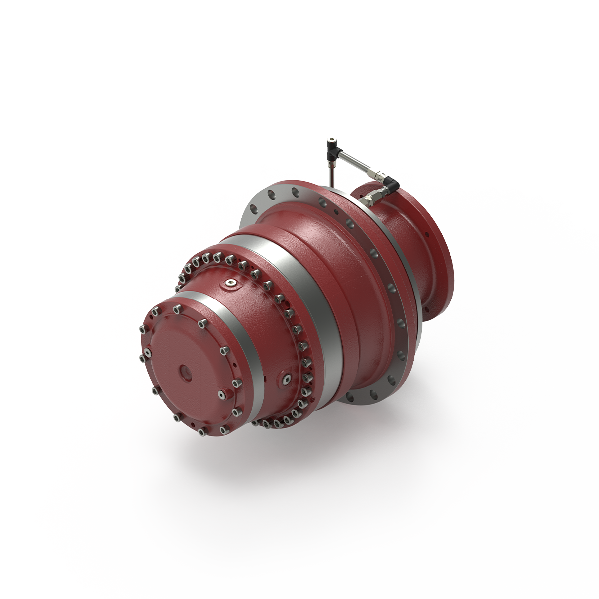
Can you provide insights into the importance of proper installation and alignment of winch drives?
Proper installation and alignment of winch drives are of utmost importance to ensure optimal performance, longevity, and safety of the system. Here’s a detailed explanation of the significance of proper installation and alignment of winch drives:
- Optimal Performance:
Proper installation and alignment are crucial for achieving optimal performance of winch drives. Precise alignment ensures that the winch drive operates within its designed parameters, minimizing power losses and maximizing efficiency. Accurate installation of components, such as motors, gearboxes, and brakes, ensures that they are properly integrated and aligned with each other. This alignment reduces mechanical stress, minimizes friction, and allows for smooth and reliable operation of the winch drive, resulting in improved performance and productivity.
- Extended Lifespan:
The correct installation and alignment of winch drives contribute to their longevity. When components are misaligned or improperly installed, it can lead to excessive wear, vibration, and premature failure of critical parts. Misalignment puts additional stress on bearings, shafts, gears, and other components, causing accelerated wear and reducing their lifespan. By ensuring proper alignment during installation, the load is distributed evenly, reducing mechanical stress and increasing the lifespan of the winch drive system.
- Reduced Maintenance and Downtime:
Proper installation and alignment can significantly reduce the need for maintenance and minimize downtime. Misalignment or improper installation can cause issues such as excessive heat generation, increased friction, and misoperation of safety mechanisms. These issues can lead to frequent breakdowns and unplanned downtime, resulting in productivity losses and increased maintenance costs. By ensuring correct alignment and installation, the risk of such issues is minimized, reducing the frequency of maintenance and improving overall system uptime.
- Enhanced Safety:
The safety of personnel and equipment is a critical consideration when it comes to winch drives. Improper installation and alignment can compromise the safety of the system. Misalignment can result in unexpected movements, excessive vibrations, or loss of control, posing risks to both operators and the surrounding environment. Proper alignment ensures that the winch drive operates within its intended parameters, reducing the likelihood of malfunctions, accidents, or equipment damage. It is essential to follow manufacturer guidelines and industry standards for installation and alignment to maintain a safe working environment.
- Efficient Power Transmission:
Correct alignment of winch drives ensures efficient power transmission from the motor to the drum or load. Misalignment can lead to power losses, increased energy consumption, and reduced overall system efficiency. Proper alignment ensures that the power is transmitted smoothly and efficiently, minimizing energy wastage and optimizing the performance of the winch drive. This not only improves energy efficiency but also reduces operating costs over the lifespan of the system.
In summary, the proper installation and alignment of winch drives are essential for achieving optimal performance, extending the lifespan of the system, reducing maintenance and downtime, enhancing safety, and ensuring efficient power transmission. Following manufacturer guidelines, industry standards, and engaging experienced professionals during installation and alignment processes is crucial to maximize the benefits and longevity of winch drive systems.
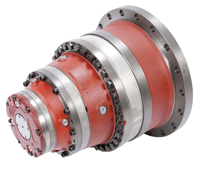
How does the design of winch drives impact their performance in different environments?
The design of winch drives plays a critical role in determining their performance in different environments. Various design factors influence the reliability, efficiency, and adaptability of winch drives to specific operating conditions. Here’s a detailed explanation of how the design of winch drives impacts their performance:
- Load Capacity and Power:
The design of winch drives directly affects their load capacity and power capabilities. Factors such as motor size, gear ratio, and drum diameter determine the maximum load capacity a winch drive can handle. The power output of the motor and the mechanical advantage provided by the gear system impact the winch drive’s ability to lift or pull heavy loads effectively. A well-designed winch drive with appropriate load capacity and power ensures optimal performance in different environments.
- Speed and Control:
The design of winch drives influences their speed and control characteristics. The gear ratio and motor specifications determine the speed at which the winch drive can operate. Additionally, the presence of a variable speed control mechanism allows for precise and controlled movement of loads. The design should strike a balance between speed and control, depending on the specific application and operational requirements in different environments.
- Drive System:
Winch drives can utilize different drive systems, such as electric, hydraulic, or pneumatic. The design of the drive system impacts the performance of the winch drive in different environments. Electric winch drives are commonly used due to their ease of use, precise control, and suitability for various applications. Hydraulic winch drives offer high power output and are often preferred in heavy-duty applications. Pneumatic winch drives are suitable for environments where electricity or hydraulics are not readily available. The design should align with the specific requirements and constraints of the environment in which the winch drive will be used.
- Enclosure and Protection:
The design of the winch drive enclosure and protection features significantly impacts its performance in different environments. Winch drives used in outdoor or harsh environments should have robust enclosures that provide protection against dust, moisture, and other contaminants. Sealed or weatherproof enclosures prevent damage to internal components and ensure reliable operation. Additionally, features such as thermal protection and overload protection are designed to safeguard the winch drive from overheating or excessive strain, enhancing its performance and longevity.
- Mounting and Installation:
The design of winch drives should consider the ease of mounting and installation. Mounting options such as bolt-on, weld-on, or integrated mounting plates offer flexibility for different installation scenarios. The design should also take into account the space constraints and mounting requirements of the specific environment. Easy and secure installation ensures proper alignment, stability, and efficient operation of the winch drive.
- Control and Safety Features:
The design of winch drives includes control and safety features that impact their performance in different environments. Control systems can range from simple push-button controls to advanced remote controls or integrated control panels. The design should provide intuitive and user-friendly control interfaces for efficient operation. Safety features such as emergency stop mechanisms, load limiters, and overload protection are crucial to prevent accidents and ensure safe operation in various environments. The design should prioritize the incorporation of appropriate safety features based on the specific application and environmental conditions.
By considering these design factors, winch drives can be optimized for performance, reliability, and safety in different environments. A well-designed winch drive that aligns with the specific requirements of the environment will deliver efficient and effective lifting or pulling capabilities while ensuring long-term durability and functionality.
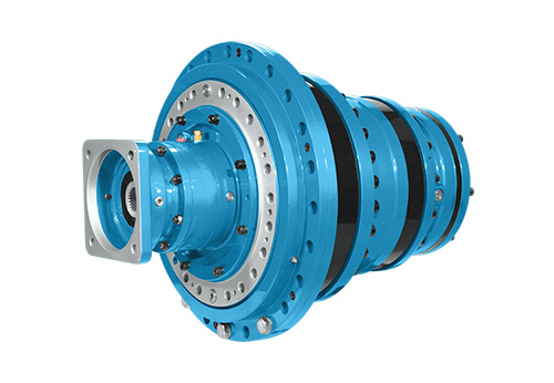
Can you explain the key components and functions of a winch drive mechanism?
A winch drive mechanism consists of several key components that work together to provide controlled pulling or lifting capabilities. Each component has a specific function that contributes to the overall operation of the winch drive. Here’s a detailed explanation of the key components and their functions:
- Power Source:
The power source is the component that provides the energy to drive the winch mechanism. It can be an electric motor, hydraulic system, or even a manual crank. Electric motors are commonly used in modern winches due to their efficiency, controllability, and ease of operation. Hydraulic systems are often employed in heavy-duty winches that require high pulling capacities. Manual winches, operated by hand-cranking, are typically used in lighter applications or as backup systems. The power source converts the input energy into rotational motion, which drives the other components of the winch mechanism.
- Gearbox or Transmission:
The gearbox or transmission is responsible for controlling the speed and torque output of the winch drive. It consists of a series of gears arranged in specific ratios. The gears are engaged or disengaged to achieve the desired speed and torque requirements for the application. The gearbox allows the winch drive to provide both high pulling power or low-speed precision, depending on the needs of the task. It also helps distribute the load evenly across the gear teeth, ensuring smooth and reliable operation.
- Drum or Spool:
The drum or spool is a cylindrical component around which the cable or rope is wound. It is typically made of steel or other durable materials capable of withstanding high tension forces. The drum is connected to the rotational output of the gearbox or transmission. As the gearbox rotates, the drum winds or unwinds the cable, depending on the direction of rotation. The diameter of the drum determines the pulling or lifting capacity of the winch drive. A larger drum diameter allows for a greater length of cable to be wound, resulting in increased pulling power.
- Cable or Rope:
The cable or rope is the element that connects the winch drive to the load being pulled or lifted. It is typically made of steel wire or synthetic materials with high tensile strength. The cable is wound around the drum and extends out to the anchor point or attachment point of the load. It acts as the link between the winch drive and the object being moved. The choice of cable or rope depends on the specific application requirements, such as the weight of the load, environmental conditions, and desired flexibility.
- Braking System:
A braking system is an essential component of a winch drive mechanism to ensure safe and controlled operation. It prevents the cable or rope from unwinding uncontrollably when the winch is not actively pulling or lifting a load. The braking system can be mechanical or hydraulic, and it engages automatically when the winch motor is not applying power. It provides a secure hold and prevents the load from slipping or releasing unintentionally. The braking system also helps control the descent of the load during lowering operations, preventing sudden drops or free-falls.
- Control System:
The control system allows the operator to manage the operation of the winch drive. It typically includes controls such as switches, buttons, or levers that enable the activation, direction, and speed control of the winch. The control system can be integrated into the winch housing or provided as a separate control unit. In modern winches, electronic control systems may offer additional features such as remote operation, load monitoring, and safety interlocks. The control system ensures precise and safe operation, allowing the operator to adjust the winch drive according to the specific requirements of the task.
In summary, a winch drive mechanism consists of key components such as the power source, gearbox or transmission, drum or spool, cable or rope, braking system, and control system. The power source provides the energy to drive the winch, while the gearbox controls the speed and torque output. The drum or spool winds or unwinds the cable, which connects the winch drive to the load. The braking system ensures safe and controlled operation, and the control system allows the operator to manage the winch’s performance. Together, these components enable winch drives to provide controlled pulling or lifting capabilities in a wide range of applications.


editor by Dream 2024-05-07
China 12V 24 V DC Gear Motor Hollow Plastic Gear for Electric Height Adjustable Desk Motor Mini Brush Table Lift Motor helical worm gearbox
Error:获取session失败,
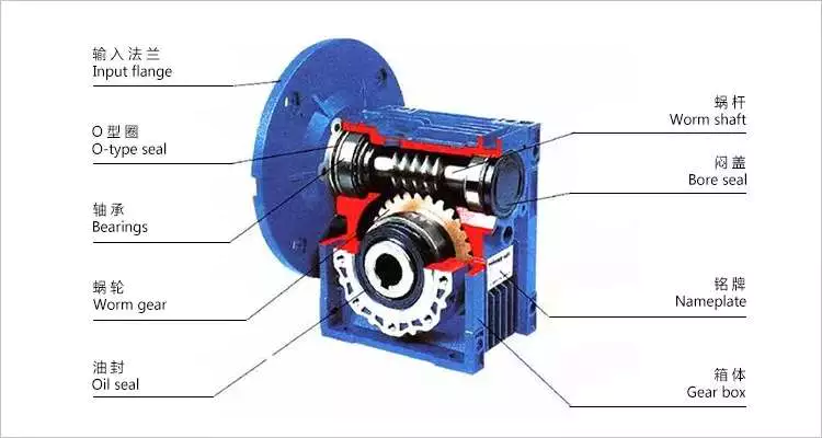
Worm reducer gearbox
Worm reducer gearboxes are commonly used to reduce the Agknx produced by a rotating shaft. They can achieve reduction ratios of five to sixty. In contrast, a single-stage hypoid gear can achieve up to a 120:1 reduction ratio. For further reduction, another type of gearing is used. So, a single stage worm reducer gearbox cannot achieve higher ratios than these.
Mechanics
A worm reducer gearbox is an auxiliary mechanical device that uses worms to reduce the size of a rotating shaft. These worms have a range of tooth forms. One form is a line weave twist surface. Another is a trapezoid based on a central cross section. The trapezoid can be perpendicular to the tooth cross section, or it can be normal to the root cross section. Other forms include involute helicoids and convolute worms, which use a straight line intersecting the involute generating line.
Worm gears are lubricated with a special lubricant. Because worm gears are complex, it’s important to use the correct lubricant. Worm gear manufacturers provide approved lubricants for their gears. Using unapproved gear oil can damage your reducer gearbox’s efficiency. The right lubricant depends on several factors, including load, speed, duty cycle, and expected operating temperatures.
The efficiency of a worm gear reducer gearbox depends on several factors, including losses at gear mesh, losses in the bearings, and windage in the oil seal lip. In addition, the worm gear reducer gearbox’s efficiency varies with ambient temperature and operating temperature. The worm gear reducer gearbox’s efficiency can also vary with the ratio of the load. Moreover, worm gear reducer gearboxes are subject to break-in.
Worm gear reducer gearboxes are used in many different applications. They are typically used in small electric motors, but they’re also used in conveyor systems, presses, elevators, and mining applications. Worm gears are also commonly found in stringed musical instruments.
Worm gears have excellent reduction ratios and high Agknx multiplication, and they’re often used as speed reducer gearboxes in low to medium-speed applications. However, the efficiency of worm gear reducer gearboxes decreases with increasing ratios.
Sizes
Worm reducer gearboxes come in different sizes and tooth shapes. While the tooth shape of one worm is similar to the other, different worms are designed to carry a different amount of load. For example, a circular arc worm may have a different tooth shape than one with a secondary curve. Worm gears can also be adjusted for backlash. The backlash is the difference between the advancing and receding arc.
There are two sizes of worm reducer gearboxes available from Agknx Transmission. The SW-1 and SW-5 models offer ratios of 3.5:1 to 60:1 and 5:1 to 100:1 respectively. The size of the worm reducer gearbox is determined by the required gear ratio.
Worm gears have different thread counts. One is based on the central cross-section of the worm, and the other is on the right. Worm gears can have either a single or double thread. Single-threaded gears will reduce speed by 50 percent, while double-threaded gears will reduce speed by 25 percent.
Worm gear reducer gearboxes are lightweight and highly reliable. They can accommodate a variety of NEMA input flanges and hollow output bore sizes. Worm reducer gearboxes can be found at 6 regional warehouses, with prepaid freight. To make a purchasing decision, you should consider the horsepower and Agknx requirements of your specific application.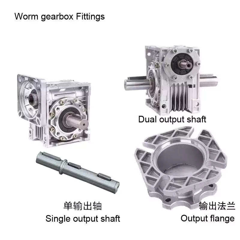
Applications
The Worm reducer gearbox market is a global business that is dominated by the North American and European regions. The report provides in-depth information on the market trends, key challenges, and opportunities. It also examines the current state of the industry and projects future market growth. The report is organized into segments based on product type, major geographical regions, and application. It also presents statistics and key data about the market.
Worm gear reducer gearboxes have many applications. They can be used to increase the speed of convey belts. They also help reduce noise. Worm gears have many teeth that touch the gear mesh, which makes them quieter. Moreover, the worm gears require only a single stage reducer gearbox, reducing the number of moving parts in the system.
The worm gear has long life and is suitable for different industries. It is a perfect choice for elevators and other applications that need fast stopping and braking. Its compact size and ability to hold a load make it suitable for these applications. It also prevents the load from free-falling as a result of a sudden braking. Worm gears can also be used in heavy-duty machinery such as rock crushers.
Worm gears are similar to ordinary gears except that they transfer motion at a 90-degree angle. As a result, the worm gears are extremely quiet, making them a suitable option for noise sensitive applications. They are also excellent for low-voltage applications, where the noise is critical.
Worm gears are ideal for applications with space restrictions, because they require fewer gear sets. The worm gears also allow for a smaller gearbox size. Consequently, they are the perfect choice for machines that are space-constrained, such as conveyors and packaging equipment.
Cost
The lifespan of a worm gear reducer gearbox is comparable to other gear reducer gearboxes. Worm gears have a long history of innovation and use in various industries, from shipbuilding to automobile manufacturing. Today, these gear reducer gearboxes are still popular with engineers. However, there are some things to keep in mind before buying one.
In the first place, a worm reducer gearbox needs to be affordable. Generally, a worm reducer gearbox costs about $120. The price varies with the brand name and features. Some products are more expensive than others, so be sure to shop around for the best price. In addition, it is important to consider the quality and design of the worm reducer gearbox before making a purchase.
Worm gear manufacturers have made significant advancements in materials, design and manufacturing. These advancements, along with the use of advanced lubricants, have resulted in significant increases in efficiency. For example, double enveloping worm gear reducer gearboxes have improved efficiency by three to eight percentage points. This improvement was achieved through rigorous testing of manufacturing processes and materials. With these improvements, worm gear reducer gearboxes have become more desirable in today’s market.
Worm reducer gearboxes are extremely versatile and reliable, and are available in a variety of sizes. Domestic manufacturers usually stock a large selection of reducer gearboxes, and are often able to ship them the same day you place your order. Most major domestic worm gear reducer gearbox manufacturers also share some critical mounting dimensions, such as the output shaft diameter, the mounting hole location, and the overall reducer gearbox housing height. Most manufacturers also offer standardized gear ratios. Some manufacturers have also improved gear design and added synthetic lubricants for better performance.
In addition, different tooth shapes of worms can increase their load carrying capacity. They can be used on secondary curves and circular arc cross sections. Moreover, the pitch point defines the boundary of the cross section. The mesh on the receding arc is smoother than that of the advancing arc. However, in the case of negative shifting, most of the mesh is on the receding arc.
Self-locking function
A worm reducer gearbox has a self-locking function. When a worm is fitted with all of its addendum teeth, the total number of teeth in the system should be greater than 40. This self-locking function is achieved through the worm’s rack and pinion mechanism. The worm’s self-locking feature can prevent the load from being dropped and is useful for many applications.
The self-locking function of a worm reducer gearbox is possible for two main reasons. First of all, a worm reducer gearbox uses two or more gears. One gear is placed at the input, and the other gear runs the output shaft. This mechanism produces a torque, which is transmitted to a spur gear.
Worm reducer gearboxes can be used in a variety of industrial applications. Because of their self-locking function, they are useful for preventing back-driving. They are also helpful for lifting and holding loads. Their self-locking mechanism allows for a large gear reduction ratio without increasing the size of a gear box.
Self-locking gears can be used to prevent back-driving and inertial driving. This is useful for many industries and can prevent backdriving. However, one major disadvantage of self-locking gears is their sensitivity to operating conditions. Lubrication, vibration, and misalignment can affect their reliability.
Embodiments of the invention provide a self-locking mechanism that prevents back-driving but allows forward-driving. The self-locking mechanism may comprise first and second ratchet cams disposed about a gear member. A releasable coupling member may be interposed between the gear member and the ratchet cam. This facilitates selective coupling and decoupling.
The worm reducer gearbox has several advantages. Its compact design is ideal for many mechanical transmission systems. It also provides greater load capacity than a cross-axis helical gear mechanism.


editor by CX 2023-04-23