Product Description
CV and CH series motor can be designed as Single phase and 3 phases type. And power range is from 0.1KW to 3.7KW. The motor can be mounted with brake, and brake type is No excitation type. Material of gears is advanced special alloy steel and all gears are carburizing hardening. This gear motor has been added with senior lubricants, and no needs to added lubricants again.
Helical gear reducer has the characteristics of strong versatility, good combination, and strong bearing capacity, and has the advantages of easy access to various transmission ratios, high efficiency, small vibration, and high allowable axial and radial loads.
This series of products can not only be used in combination with various reducers and vibrators to meet the requirements, but also has the advantage of localization of related transmission equipment.
Mostly used in metallurgy, sewage treatment,chemical, pharmaceutical and other industries.
| Type | CH series three phase or single phase ac motors for industrial use | |
| Voltage | 220VAC, 380VAC, 415VAC | |
| Power range | Power range is 0.1KW to 3.7KW | |
| Output Speed | Speed range is from 7rpm to 500rpm | |
| Phase | Single phase and 3phases for choice | |
| Gears | Special alloy steel and high precise gears | |
| Grease | Good grease and no need add grease during using | |
| Cooling | Full closed fan | |
| USE | This motor is widely used in packing machine, textil machine |
motor is widely used in mix machine,elevator, conveyor,etc. |
| OEM Service | We offer OEM service. | |
/* January 22, 2571 19:08:37 */!function(){function s(e,r){var a,o={};try{e&&e.split(“,”).forEach(function(e,t){e&&(a=e.match(/(.*?):(.*)$/))&&1
| Application: | Motor, Machinery, Agricultural Machinery |
|---|---|
| Hardness: | Hardened Tooth Surface |
| Installation: | Vertical Type |
| Layout: | Coaxial |
| Gear Shape: | Bevel Gear |
| Step: | Three-Step |
| Samples: |
US$ 70/Piece
1 Piece(Min.Order) | |
|---|
| Customization: |
Available
|
|
|---|
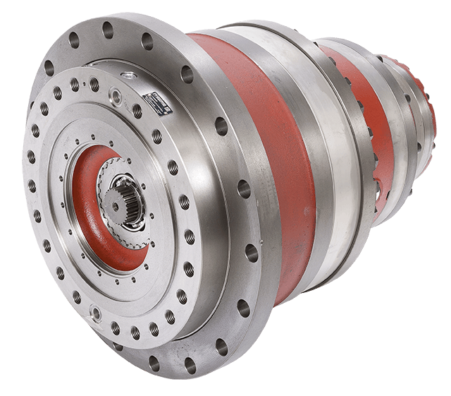
How does the choice of winch drives affect the overall performance and reliability of lifting operations?
The choice of winch drives has a significant impact on the overall performance and reliability of lifting operations. Here’s a detailed explanation of how the choice of winch drives affects performance and reliability:
- Lifting Capacity:
The choice of winch drives directly affects the lifting capacity of the system. Different winch drives have varying load capacities, and selecting an appropriate winch drive that matches the intended lifting requirements is crucial. Choosing a winch drive with insufficient lifting capacity can result in overloading, which can lead to equipment failure, safety hazards, and potential damage to the load or surrounding structures. On the other hand, selecting a winch drive with a higher lifting capacity than necessary can lead to unnecessary costs and inefficient operation. Therefore, selecting the right winch drive with the appropriate lifting capacity is essential for optimal performance and reliability.
- Speed and Control:
The choice of winch drives also affects the speed and control of lifting operations. Different winch drives offer varying speed ranges and control options. High-quality winch drives provide smooth and precise speed control, allowing for accurate positioning and delicate handling of loads. The choice of winch drives with suitable speed and control capabilities ensures efficient and controlled lifting operations, reducing the risk of accidents, damage to the load, or strain on the lifting equipment. Additionally, winch drives with advanced control features, such as programmable logic controllers (PLCs) or electronic control systems, enhance operational reliability and performance by enabling synchronized movements and automation.
- Durability and Reliability:
The choice of winch drives significantly impacts the durability and reliability of lifting operations. High-quality winch drives constructed with robust materials and designed for heavy-duty applications offer enhanced durability and reliability. They can withstand the demanding conditions and stress associated with lifting operations, minimizing the risk of breakdowns, malfunctions, or premature wear. Choosing winch drives from reputable manufacturers known for their quality and reliability ensures long-term performance and reduces the need for frequent maintenance or replacement, enhancing the overall reliability of the lifting operations.
- Safety Features:
Winch drives come with various safety features that contribute to the overall performance and reliability of lifting operations. These safety features include overload protection systems, emergency stop controls, limit switches, and fail-safe mechanisms. The choice of winch drives with comprehensive safety features enhances the safety of lifting operations by preventing overloading, safeguarding against equipment failures, and providing emergency shutdown options in critical situations. Properly selecting winch drives with appropriate safety features ensures compliance with safety regulations, reduces the risk of accidents, and enhances the reliability of lifting operations.
- Compatibility and Integration:
Choosing winch drives that are compatible with the overall lifting system and easily integrable with other components is crucial for optimal performance and reliability. Compatibility issues can arise if the selected winch drive does not match the mechanical requirements, power supply, or control interfaces of the lifting system. Incompatibility can lead to operational inefficiencies, increased maintenance needs, or even system failures. Therefore, careful consideration of the compatibility and integration aspects when choosing winch drives ensures seamless integration, smooth operation, and enhanced reliability of lifting operations.
In summary, the choice of winch drives significantly impacts the overall performance and reliability of lifting operations. Factors such as lifting capacity, speed and control capabilities, durability and reliability, safety features, and compatibility with the overall system should be carefully considered when selecting winch drives. By choosing the right winch drives that meet the specific requirements of the lifting operations, operators can achieve optimal performance, ensure safe and efficient lifting, and enhance the overall reliability of the operations.
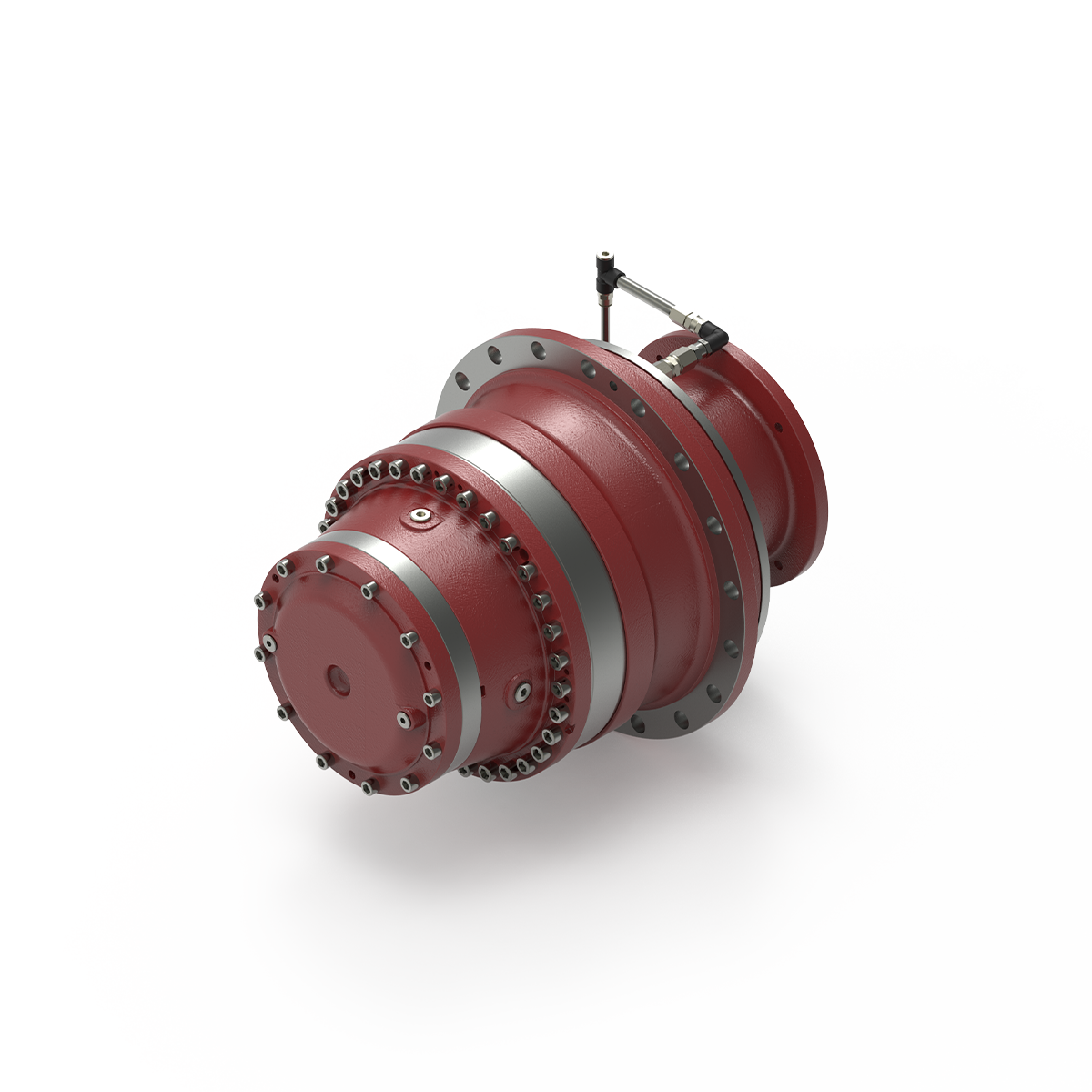
What safety considerations should be taken into account when using winch drives?
Using winch drives involves certain safety considerations to ensure the well-being of operators, prevent accidents, and protect the equipment and the load being lifted. Here’s a detailed explanation of the safety considerations that should be taken into account when using winch drives:
- Operator Training:
Proper training is essential for operators who will be using winch drives. They should receive comprehensive training on the safe operation of winch drives, including understanding the controls, procedures, safety features, and potential hazards. Training should cover load calculations, safe working loads, and the importance of following safety guidelines and manufacturer’s instructions.
- Equipment Inspection:
Prior to each use, winch drives should be thoroughly inspected to ensure they are in proper working condition. This includes checking for any signs of damage, wear, or corrosion. The cables or ropes should be inspected for fraying, kinks, or other defects. Any damaged or malfunctioning components should be repaired or replaced before operating the winch drive.
- Load Capacity:
It is crucial to adhere to the specified load capacity of the winch drive. Exceeding the maximum load capacity can lead to equipment failure, accidents, and injuries. Operators should accurately determine the weight of the load to be lifted and ensure it falls within the winch drive’s rated capacity. If the load exceeds the capacity, alternative lifting methods or equipment should be used.
- Secure Anchoring:
Winch drives should be securely anchored to a stable and appropriate mounting point. This ensures that the winch drive remains stable during operation and prevents unintended movement. The anchoring point should be capable of withstanding the forces generated during lifting or pulling operations. Proper anchoring minimizes the risk of equipment tipping over or shifting unexpectedly.
- Personal Protective Equipment (PPE):
Operators should wear appropriate personal protective equipment (PPE) when using winch drives. This may include safety helmets, gloves, eye protection, and high-visibility clothing. PPE helps protect operators from potential hazards such as falling objects, flying debris, or contact with moving parts. The specific PPE requirements should be determined based on the nature of the lifting operation and any applicable safety regulations.
- Safe Operating Distance:
Operators and other personnel should maintain a safe distance from the winch drive during operation. This prevents accidental contact with moving parts or the load being lifted. Clear warning signs or barriers should be used to define the restricted area around the winch drive. Operators should never place themselves or others in the potential path of the load or in a position where they could be struck by the load in case of a failure or slippage.
- Emergency Stop and Controls:
Winch drives should be equipped with emergency stop mechanisms or controls that allow operators to quickly halt the operation in case of an emergency. All operators should be familiar with the location and operation of the emergency stop controls. Regular testing and maintenance of these controls are essential to ensure their effectiveness in emergency situations.
- Proper Rigging and Rigging Techniques:
Correct rigging techniques should be followed when attaching the load to the winch drive. This includes using appropriate slings, hooks, or attachments and ensuring they are properly secured. Improper rigging can lead to load instability, shifting, or falling, posing a significant safety risk. Operators should be trained in proper rigging techniques and inspect the rigging components for wear or damage before each use.
- Regular Maintenance:
Winch drives should undergo regular maintenance as recommended by the manufacturer. This includes lubrication, inspection of cables or ropes, checking for loose bolts or connections, and verifying the functionality of safety features. Regular maintenance helps identify and address potential issues before they lead to equipment failure or accidents.
By considering these safety measures, operators can ensure the safe and effective use of winch drives, minimizing the risk of accidents, injuries, or equipment damage. It is crucial to prioritize safety at all times and to comply with applicable safety regulations and guidelines.
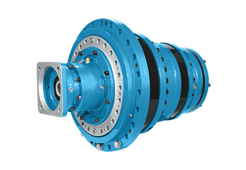
Can you explain the key components and functions of a winch drive mechanism?
A winch drive mechanism consists of several key components that work together to provide controlled pulling or lifting capabilities. Each component has a specific function that contributes to the overall operation of the winch drive. Here’s a detailed explanation of the key components and their functions:
- Power Source:
The power source is the component that provides the energy to drive the winch mechanism. It can be an electric motor, hydraulic system, or even a manual crank. Electric motors are commonly used in modern winches due to their efficiency, controllability, and ease of operation. Hydraulic systems are often employed in heavy-duty winches that require high pulling capacities. Manual winches, operated by hand-cranking, are typically used in lighter applications or as backup systems. The power source converts the input energy into rotational motion, which drives the other components of the winch mechanism.
- Gearbox or Transmission:
The gearbox or transmission is responsible for controlling the speed and torque output of the winch drive. It consists of a series of gears arranged in specific ratios. The gears are engaged or disengaged to achieve the desired speed and torque requirements for the application. The gearbox allows the winch drive to provide both high pulling power or low-speed precision, depending on the needs of the task. It also helps distribute the load evenly across the gear teeth, ensuring smooth and reliable operation.
- Drum or Spool:
The drum or spool is a cylindrical component around which the cable or rope is wound. It is typically made of steel or other durable materials capable of withstanding high tension forces. The drum is connected to the rotational output of the gearbox or transmission. As the gearbox rotates, the drum winds or unwinds the cable, depending on the direction of rotation. The diameter of the drum determines the pulling or lifting capacity of the winch drive. A larger drum diameter allows for a greater length of cable to be wound, resulting in increased pulling power.
- Cable or Rope:
The cable or rope is the element that connects the winch drive to the load being pulled or lifted. It is typically made of steel wire or synthetic materials with high tensile strength. The cable is wound around the drum and extends out to the anchor point or attachment point of the load. It acts as the link between the winch drive and the object being moved. The choice of cable or rope depends on the specific application requirements, such as the weight of the load, environmental conditions, and desired flexibility.
- Braking System:
A braking system is an essential component of a winch drive mechanism to ensure safe and controlled operation. It prevents the cable or rope from unwinding uncontrollably when the winch is not actively pulling or lifting a load. The braking system can be mechanical or hydraulic, and it engages automatically when the winch motor is not applying power. It provides a secure hold and prevents the load from slipping or releasing unintentionally. The braking system also helps control the descent of the load during lowering operations, preventing sudden drops or free-falls.
- Control System:
The control system allows the operator to manage the operation of the winch drive. It typically includes controls such as switches, buttons, or levers that enable the activation, direction, and speed control of the winch. The control system can be integrated into the winch housing or provided as a separate control unit. In modern winches, electronic control systems may offer additional features such as remote operation, load monitoring, and safety interlocks. The control system ensures precise and safe operation, allowing the operator to adjust the winch drive according to the specific requirements of the task.
In summary, a winch drive mechanism consists of key components such as the power source, gearbox or transmission, drum or spool, cable or rope, braking system, and control system. The power source provides the energy to drive the winch, while the gearbox controls the speed and torque output. The drum or spool winds or unwinds the cable, which connects the winch drive to the load. The braking system ensures safe and controlled operation, and the control system allows the operator to manage the winch’s performance. Together, these components enable winch drives to provide controlled pulling or lifting capabilities in a wide range of applications.


editor by Dream 2024-04-24
China 1440 Rpm Cast Iron Speed Reducer High Speed Worm Gearbox Single Stage WPO Serie Small Worm Gearboxes aluminum worm gearbox
Guarantee: 1 many years
Relevant Industries: Garment Outlets, Creating Materials Stores, Equipment Fix Retailers, Food & Beverage Factory, Farms, Food Store, Design works , Other
Weight (KG): 15 KG
Tailored assistance: OEM, ODM, OBM
Gearing Arrangement: Worm
Output Torque: 6M810 Engine timing camshaft sprocket 24370-2M8M800 is ideal for Sonata, CZPT Lion Operate and Sorento. we can layout non-common merchandise according to customers’ drawings and samples. Q:What is the payment time period?A:T/T and Paypal is utilized more,you should speak to us for particulars Q: How lengthy is the shipping and delivery date?A: 10 – 20 enterprise days.
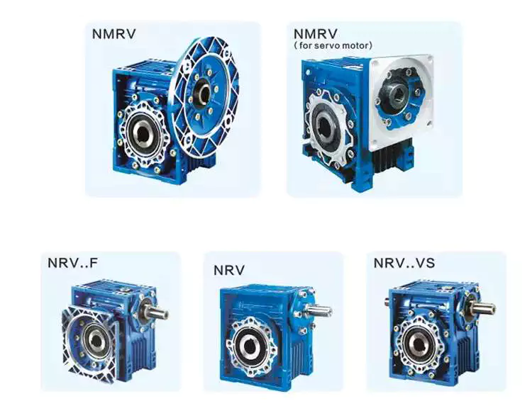
Worm gear reducer gearbox
A worm gear reducer gearbox is a gear reducer gearbox that uses a worm gear train to reduce the required force. Unlike traditional gear reducer gearboxes, these units are small and require low horsepower ratings. This reduces their efficiency, but their low cost and compact design help make up for this shortcoming. However, these gear reducer gearboxes have some drawbacks, including their tendency to lock up when reversing.
high efficiency
High-efficiency worm reducer gearboxes are ideal for applications where high performance, repeatability, and accuracy are critical. It consists of an input hypoid gear and an output hypoid bevel gear. The input worm rotates perpendicular to the output worm, so for every revolution of the input worm, the output gear makes one revolution. This arrangement reduces friction (another source of energy loss) in a high-efficiency worm gear to at least two arc minutes.
Compared with worm gear reducer gearboxes, hypoid gearmotors offer several advantages, including lower operating costs and higher efficiency. For example, hypoid gear motors can transmit more torque even at high reduction ratios. Also, they are more efficient than worm gear reducer gearboxes, which means they can produce the same output with a smaller motor.
In recent years, the efficiency of worm gear reducer gearboxes has been dramatically improved. Manufacturers have made great strides in materials, design, and manufacturing. New designs, including dual-enveloping worm gear reducer gearboxes, increase efficiency by 3 to 8 percent. These improvements were made possible through countless hours of testing and development. Worm gear reducer gearboxes also offer lower initial costs and higher overload capability than competing systems.
Worm gear reducer gearboxes are popular because they provide maximum reduction in a small package. Their compact size makes them ideal for low to medium-horsepower applications and they are reticent. They also offer higher torque output and better shock load tolerance. Finally, they are an economical option to reduce the device’s power requirements.
low noise
Low-noise worm gear reducer gearboxes are designed to reduce noise in industrial applications. This type of reducer gearbox uses fewer bearings and can work in various mounting positions. Typically, a worm reducer gearbox is a single-stage unit with only one shaft and one gear. Since there is only one gear, the noise level of the worm gear reducer gearbox will be lower than other types.
A worm gear reducer gearbox can be integrated into the electric power steering system to reduce noise. Worm reducer gearboxes can be made and from many different materials. The following three-stage process will explain the components of a low-noise worm reducer gearbox.
Worm gear reducer gearboxes can be mounted at a 90-degree angle to the input worm shaft and are available with various types of hollow or solid output shafts. These reducer gearboxes are especially beneficial for applications where noise reduction is essential. They also have fewer parts and are smaller than other types of reducer gearboxes, making them easier to install.
Worm gear reducer gearboxes are available from various manufacturers. Due to their widespread availability, gear manufacturers maintain extensive inventories of these reducer gearboxes. The worm gear ratio is standard, and the size of the worm gear reducer gearbox is universal. Also, worm gear reducer gearboxes do not need to be sized for a specific purpose, unlike other load interruptions.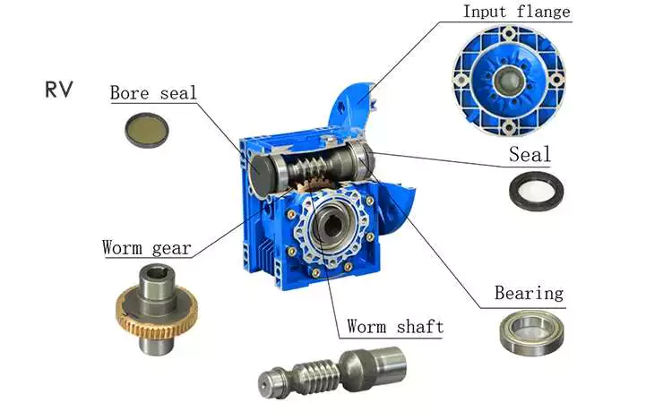
A worm gear reducer gearbox is a transmission mechanism with a compact structure, large transmission ratio, and self-locking function under certain conditions. The worm gear reducer gearbox series products are designed with American technology and have the characteristics of stable transmission, strong bearing capacity, low noise, and compact structure. In addition, these products can provide a wide range of power supplies. However, these worm reducer gearboxes are prone to leaks, usually caused by design flaws.
Worm gear reducer gearboxes are available in single-stage and double-stage. The first type consists of an oil tank that houses the worm gear and bearings. The second type uses a worm gear with a sleeve for the first worm gear.
When choosing a gear reducer gearbox, it is essential to choose a high-quality unit. Improper gear selection can cause rapid wear of the worm gear. While worm gear reducer gearboxes are generally durable, their degree of wear depends on the selection and operating conditions. For example, overuse, improper assembly, or working in extreme conditions can lead to rapid wear.
Worm reducer gearboxes reduce speed and torque. Worm gears can be used to reduce the speed of rotating machines or inertial systems. Worm gears are a type of bevel gear, and their meshing surfaces have great sliding force. Because of this, worm gears can carry more weight than spur gears. They are also harder to manufacture. However, the high-quality design of the worm gear makes it an excellent choice for applications requiring high torque and high-speed rotation.
Worm gears can be manufactured using three types of gears. For large reduction ratios, the input and output gears are irreversible. However, the worm reducer gearbox can be constructed with multiple helices. The multi-start worm drive also minimizes braking effects.
Self-locking function
The worm reducer gearbox is self-locking to prevent the load from being driven back to the ground. The self-locking function is achieved by a worm that meshes with the rack and pinion. When the load reaches the highest position, the reverse signal is disabled. The non-locking subsystem back-drives the load to its original position, while the self-locking subsystem remains in its uppermost position.
The self-locking function of the worm reducer gearbox is a valuable mechanical feature. It helps prevent backing and saves the cost of the braking system. Additionally, self-locking worm gears can be used to lift and hold loads.
The self-locking worm gear reducer gearbox prevents the drive shaft from driving backward. It works with the axial force of the worm gear. A worm reducer gearbox with a self-locking function is a very efficient machine tool.
Worm gear reducer gearboxes can be made with two or four teeth. Single-ended worms have a single-tooth design, while double-ended worms have two threads on the cylindrical gear. A multi-boot worm can have up to four boots. Worm reducer gearboxes can use a variety of gear ratios, but the main advantage is their compact design. It has a larger load capacity than a cross-shaft helical gear mechanism.
The self-locking function of the worm reducer gearbox can also be used for gear sets that are not necessarily parallel to the shaft. It also prevents backward travel and allows forward travel. The self-locking function is achieved by a ratchet cam arranged around the gear member. It also enables selective coupling and decoupling between gear members.
high gear ratio
Worm reducer gearboxes are an easy and inexpensive way to increase gear ratios. These units consist of two worm gears – an input worm gear and an output worm gear. The input worm rotates perpendicular to the output worm gear, which also rotates perpendicular to itself. For example, a 5:1 worm gearbox requires 5 revolutions per worm gear, while a 60:1 worm gearbox requires 60 revolutions. However, this arrangement is prone to inefficiency since the worm gear experiences only sliding friction, not rolling friction.
High-reduction applications require many input revolutions to rotate the output gear. Conversely, low input speed applications suffer from the same friction issues, albeit with a different amount of friction. Worms that spin at low speeds require more energy to maintain their movement. Worm reducer gearboxes can be used in many types of systems, but only some are suitable for high-speed applications.
Worm gears are challenging to produce, but the envelope design is the best choice for applications requiring high precision, high efficiency, and minimal backlash. Envelope design involves modifying gear teeth and worm threads to improve surface contact. However, this type of worm gear is more expensive to manufacture.
Worm gear motors have lower initial meshing ratios than hypoid gear motors, which allows the use of smaller motors. So a 1 hp worm motor can achieve the same output as a 1/2 hp motor. A study by Agknx compared two different types of geared motors, comparing their power, torque, and gear ratio. The results show that the 1/2 HP hypoid gear motor is more efficient than the worm gear motor despite the same output.
Another advantage of the worm gear reducer gearbox is the low initial cost and high efficiency. It offers high ratios and high torque in a small package, making it ideal for low to medium-horsepower applications. Worm gear reducer gearboxes are also more shock-resistant.

editor by Cx 2023-06-19
china sales Gear Reducer Box Gearbox Reducer Speed Drive Reduction Electric Motor Good Price Transmission Prices Variator Sumitomo Excavator High Rpm China Gear Reducer Box manufacturers
Product Description
Gear Reducer Box Gearbox Reducer CZPT CZPT Reduction CZPT ctric CZPT CZPT Cost Transmission Prices Variator CZPT Excavator CZPT Rpm CZPT Gear Reducer Box
EP also sells equipment tooth measuring devices named gear gauges! Equipment gauges lessen errors, saving time and money when determining and purchasing gears. These pitch templates have nine groups to decide all normal pitch dimensions: Diameter Pitch “DP”, Circle Pitch “CP”, External Involute Spline, Metric Modulus “MOD”, Brief Tooth, Fine Pitch, Coarse Pitch and Incredible Pitch .
china near me shop Input Speed 1500 Rpm 0.25-2.2kw 2255n. M BLE Bled141 Two Stage Cycloidal Gear Motor Speed Reducer manufacturers
Item Description
SC Transmission Cycloidal gearbox Cyclo CZPT cyc lo CZPT enter speed 1500 rpm .25-2.2kw 2255N.m BLE BLED141 two stage cycloidal equipment motor pace reducer
Merchandise Description
Cyclo CZPT are unsurpassed where generate technological innovation is anxious. The Cyclo travel is exceptional to classic gear mechanisms, since it only operates with rolling force and is not uncovered to shear forces. By comparison with gears with contact masses, Cyclo drives are more resistant and can soak up excessive shock loads by signifies of uniform load distribution over the CZPT transmitting factors. Cyclo drives and Cyclo travel geared motors are characterised by their trustworthiness, CZPT service lifestyle and excellent efficiency, even below hard circumstances.
Apps:Conveyor programs,Foodstuff and sugar industry,Mixers and agitators,Metalworking machines,Water treatment crops,Recycling crops,Poultry Processing Products,Sawmills and woodworking machines,Rolling mills,Building machinery,Paper industry
Cycloidal Reducer
Power assortment:.12-90KW
Transmission ration range:7-650000
Output torque(Kn.m):prime to thirty
Item Parameters
Business Profile
FAQ
Shipping and delivery
Worm gears are right angle drives that give large gear ratios with relatively brief center-to-middle distances from 1/4″ to 11″. When effectively mounted and lubricated, they provide as the quietest, smoothest-operating equipment sort. Simply because worm equipment drives can accomplish large equipment ratios, maximum reduction can be attained in a more compact room than numerous other varieties of gear drives. The worm and worm gear run at a 90° angle on non-intersecting axes.
china price Gear Reducer Box Gearbox Reducer Speed Drive Reduction Electric Motor Good Price Transmission Prices Variator Sumitomo Excavator High Rpm China Gear Reducer Box manufacturers
Item Description
Gear Reducer Box Gearbox Reducer CZPT CZPT Reduction CZPT ctric CZPT CZPT Cost Transmission Prices Variator CZPT Excavator CZPT Rpm CZPT Gear Reducer Box
Basic safety PROVISIONS: Worm drives should not be utilised as a locking mechanism to secure large objects, which may possibly trigger injury or harm during reverse motion. In non-probably harmful apps, self-locking is essential to avert reverse rotation, and then a low-pitch solitary-threaded worm is employed to immediately lock the worm gear to avert reverse rotation.
china near me shop Industrial Gearbox China Reducer High Rpm Helical Transmission Speed Drive Reduction Electric Motor Transmission Prices Variator Sumitomo Excavator Worm Gearbox manufacturers
Product Description
Industrial Gearbox CZPT Reducer CZPT Rpm CZPT cal Transmission CZPT CZPT Reduction CZPT ctric CZPT Transmission Charges Variator CZPT Excavator Worm Gearbox
The ideal transmission decision is when higher transmission reduction is needed. A worm equipment is similar to a helical gear with a throat reduce to improve the outer diameter of the wheel. The throat allows the worm gear to wrap totally all around the threads of the worm. By chopping the threads on the worm instead than the enamel, and by altering the quantity of threads, diverse ratios can be reached with no changing the mounting arrangement. A exclusive feature of worm gears and worm gear assemblies is their potential to avert reverse rotation.