Product Description
Model:S/SA/SAF/SF37-97
Ratio:9.96-244.74
Input Power:0.18KW-22KW.
Permissible Torque:up to 4000N.m
Mounting Mode: foot-mounted, flange-mounted, input shaft or with various types of motor direct
Company Introduction
Get the right gearbox for your equipment.
PTT knows gearbox. As the leading industry gearbox manufacturer, PSS offers the best power transmission solutions to perfectly meet your specific industry application. On gearbox, CHINAMFG has a lot more to share.
We always satisfy all industries with our gearbox
PTT strives for 100% satisfaction from customers of all industries. We welcome challenges to offer tailored design or special solution to satisfy customers’ Special needs on applications. We like to make impossibility become possibility.
Key features
Turbine gearboxes and planetary gearboxes are our advantages. Most companies can only manufacture Helical Bevel gearboxes, and we have a strong design team that has now designed turbine gearboxes up to 70, 000 rpm.
Diversity
PTT offers a vast diversity of gear reducer, geared motor and gearbox. No doubt you are able to find what you need with PTT.
Reliability
PTT is a trustworthy manufacturer you can rely on, no matter in terms of quality, delivery, pricing, service, etc. It becomes our name tag during our history of servicing our customers.
Capability
PTT is able to manufacture 200, 000 sets of gear reducers yearly and keeps investing on development of new series product.
We have a large list of our satisfied clients
Among the large list of our satisfied clients, there are many trend-setting top brands in various industries.
Mian products
Helical Gear Units
Bevel-Helical Gear Units
ZYJ Series Gear Units
DY Series Gear Units
P Planetary Gear Units
MLX Series Mill Gear Units
High Speed Gear Units
Non-stand Gear Units
RFQ
Q:Are you trading company or manufacturer?
A: We are manufacturer with over 20 years’ experience.
Q: How long is your delivery time?
A: Generally it is within 10 days if the goods are in stock, for goods produced as per order, it is within 35 days after confirmation of order.
Q: How long should I wait for the feedback after I send the enquiry?
A: Normally within 12 hours.
Q: What information should I give you to confirm the product?
A: Model/Size, Transmission Ratio, Speed, Shaft directions & Order quantity etc.
Q: Hong long is your product warranty?
A: We offer 12 months warranty from departure date of the goods.
Q: What is your payment terms? T/T 100% in advance for amount less than USD10000.-, 30% T/T in advance , balance before shipment for amount above USD10000.
If you have any other questions, please feel free to contact us below:
HOW TO CONTACT US?
Send your Inquiry Details in the Below, click “Send” Now!
/* January 22, 2571 19:08:37 */!function(){function s(e,r){var a,o={};try{e&&e.split(“,”).forEach(function(e,t){e&&(a=e.match(/(.*?):(.*)$/))&&1
| Application: | Motor, Machinery, Agricultural Machinery |
|---|---|
| Function: | Change Drive Torque, Speed Changing, Speed Reduction |
| Hardness: | Hardened Tooth Surface |
| Customization: |
Available
|
|
|---|
.shipping-cost-tm .tm-status-off{background: none;padding:0;color: #1470cc}
|
Shipping Cost:
Estimated freight per unit. |
about shipping cost and estimated delivery time. |
|---|
| Payment Method: |
|
|---|---|
|
Initial Payment Full Payment |
| Currency: | US$ |
|---|
| Return&refunds: | You can apply for a refund up to 30 days after receipt of the products. |
|---|
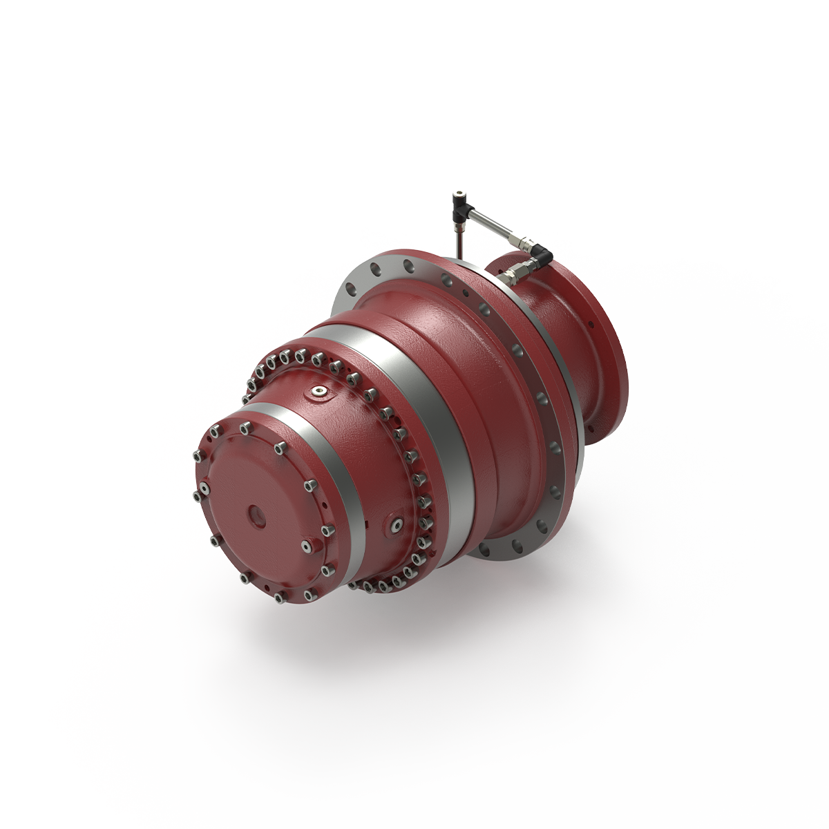
Can you explain the impact of winch drives on the overall efficiency of lifting systems?
The efficiency of lifting systems is significantly influenced by the choice and performance of winch drives. Winch drives play a crucial role in converting power into mechanical work to lift or move heavy loads. Here’s a detailed explanation of the impact of winch drives on the overall efficiency of lifting systems:
- Power Transmission:
Winch drives are responsible for transmitting power from the energy source to the lifting mechanism. The efficiency of power transmission directly affects the overall efficiency of the lifting system. Well-designed winch drives minimize power losses due to friction, heat generation, or mechanical inefficiencies. By optimizing the gear system, bearings, and other mechanical components, winch drives can maximize power transmission efficiency and minimize energy waste.
- Mechanical Advantage:
Winch drives provide a mechanical advantage that allows the lifting system to handle heavier loads with less effort. The mechanical advantage is determined by the gear ratio and drum diameter of the winch drive. By selecting an appropriate gear ratio, the winch drive can multiply the input torque, enabling the lifting system to overcome the resistance of the load more efficiently. A higher mechanical advantage reduces the strain on the power source and improves the overall efficiency of the lifting system.
- Speed Control:
Winch drives offer speed control capabilities, allowing operators to adjust the lifting speed according to the specific requirements of the task. The ability to control the lifting speed is essential for efficient and safe operation. By utilizing winch drives with precise speed control mechanisms, the lifting system can optimize the speed to match the load, reducing unnecessary energy consumption and increasing overall efficiency.
- Load Distribution:
Winch drives play a vital role in distributing the load evenly across the lifting system. Uneven load distribution can lead to excessive stress on certain components, reducing the overall efficiency and potentially causing equipment failure. Well-designed winch drives ensure that the load is distributed evenly, minimizing stress concentrations and maximizing the efficiency of the lifting system.
- Control and Safety Features:
Winch drives incorporate control and safety features that contribute to the overall efficiency of the lifting system. Advanced control systems allow for precise positioning and smooth operation, minimizing unnecessary movements and reducing energy consumption. Safety features, such as overload protection or emergency stop mechanisms, help prevent accidents and equipment damage, ensuring uninterrupted and efficient operation of the lifting system.
- Reliability and Maintenance:
The reliability and maintenance requirements of winch drives directly impact the overall efficiency of lifting systems. Well-designed winch drives with robust construction and quality components minimize the risk of breakdowns or unplanned downtime. Additionally, winch drives that are easy to maintain and service reduce the time and resources required for maintenance, maximizing the uptime and efficiency of the lifting system.
In summary, the choice and performance of winch drives have a significant impact on the overall efficiency of lifting systems. By optimizing power transmission, providing a mechanical advantage, offering speed control, ensuring load distribution, incorporating control and safety features, and prioritizing reliability and maintenance, winch drives can enhance the efficiency, productivity, and safety of lifting operations.

What factors should be considered when selecting a winch drive for specific applications?
When selecting a winch drive for specific applications, several factors need to be considered to ensure optimal performance and compatibility. Here’s a detailed explanation of the key factors that should be taken into account:
- Load Capacity:
The load capacity is one of the most critical factors to consider when selecting a winch drive. It refers to the maximum weight or force that the winch can handle safely and efficiently. It’s essential to evaluate the anticipated loads in the specific application and choose a winch drive with a sufficient load capacity to handle those loads. Selecting a winch drive with inadequate load capacity can result in safety hazards, reduced performance, and potential damage to the winch or the load being lifted or pulled.
- Power Source:
The power source of the winch drive is another crucial consideration. Winch drives are available in electric, hydraulic, and pneumatic variants, each with its own advantages and limitations. The choice of power source depends on factors such as the availability of power, the required pulling power, and the specific application’s environmental conditions. Electric winch drives are commonly used due to their ease of use and versatility. Hydraulic winch drives offer high pulling power for heavy-duty applications, while pneumatic winch drives are suitable for hazardous or explosive environments where electrical components are not permitted.
- Control Mechanisms:
The control mechanisms of the winch drive play a significant role in the efficiency and ease of operation. Consider the control options available for the winch drive, such as manual control, remote control, or integrated control systems. Remote control systems, for example, allow operators to control the winch drive from a safe distance, enhancing safety and flexibility. Additionally, some winch drives offer features like variable speed control, which allows for precise positioning and controlled movement of the load.
- Environmental Conditions:
The environmental conditions in which the winch drive will be used should be carefully assessed. Some winch drives are designed to withstand harsh environments, such as extreme temperatures, moisture, dust, or corrosive substances. For example, in marine applications, winch drives need to be corrosion-resistant and capable of operating in wet and salty conditions. Assessing the specific environmental conditions and selecting a winch drive with appropriate protection and durability features ensures its longevity and reliable performance.
- Mounting and Installation:
The mounting and installation requirements of the winch drive should be considered to ensure proper integration into the intended application. Evaluate factors such as space availability, mounting options (e.g., vehicle-mounted, structure-mounted, or portable), and compatibility with existing equipment or systems. Some winch drives may require additional accessories or modifications for installation, so it’s important to factor in these considerations during the selection process.
- Safety Features:
Winch drives should be equipped with appropriate safety features to prevent accidents and ensure secure operation. Common safety features include overload protection, emergency stop mechanisms, limit switches, and braking systems for load holding. These safety features contribute to the safe operation of the winch drive and protect against potential hazards or damage caused by excessive loads or unexpected circumstances.
- Reliability and Maintenance:
Consider the reliability and maintenance requirements of the winch drive. Look for winch drives from reputable manufacturers known for producing high-quality and reliable equipment. Assess factors such as maintenance intervals, ease of maintenance, availability of spare parts, and after-sales support. Choosing a winch drive that is reliable and has accessible maintenance options ensures minimal downtime and long-term cost-effectiveness.
By considering these factors when selecting a winch drive for specific applications, you can make an informed decision that aligns with the load requirements, power source availability, control preferences, environmental conditions, and safety considerations of your intended application.
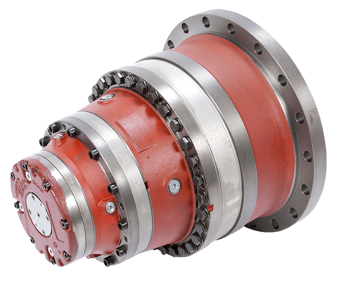
What are the advantages of using a winch drive in comparison to other lifting mechanisms?
Using a winch drive as a lifting mechanism offers several advantages over other lifting mechanisms. The unique characteristics and capabilities of winch drives make them a preferred choice in various applications. Here’s a detailed explanation of the advantages of using a winch drive in comparison to other lifting mechanisms:
- Versatility:
Winch drives offer versatility in terms of their application and adaptability to different industries. They can be utilized in a wide range of scenarios, including off-road recovery, marine operations, construction sites, and recreational activities. Winch drives can handle various load sizes and weights, making them suitable for both light and heavy lifting tasks. The ability to use winch drives in diverse environments and industries makes them a flexible and versatile choice for lifting and pulling operations.
- Control and Precision:
Winch drives provide precise control over the lifting and pulling operation. The gearing system allows operators to adjust the speed and direction of the winch drive, enabling accurate positioning and controlled movement of the load. This level of control is particularly beneficial in applications where precise load placement or delicate handling is required. Winch drives allow for fine adjustments and smooth operation, resulting in improved precision and reduced risk of damage to the load or surrounding structures.
- Pulling Power:
Winch drives are designed to generate significant pulling power, allowing them to handle heavy loads effectively. The power source, whether it’s an electric motor or hydraulic system, provides the necessary energy to generate substantial pulling force. This makes winch drives suitable for tasks that involve moving or lifting heavy objects, such as in construction, industrial settings, or vehicle recovery. The pulling power of winch drives gives them an advantage over other lifting mechanisms that may have limited capacity or require additional equipment for handling heavier loads.
- Compactness and Portability:
Winch drives are generally compact and portable, which enhances their usability in various settings. They can be easily mounted on vehicles, equipment, or structures, offering mobility and convenience. Compact winch drives are particularly useful in off-road vehicles, where space may be limited. The portability of winch drives allows for flexibility in different applications and enables their use in remote or challenging locations where other lifting mechanisms may not be easily accessible.
- Safety:
Winch drives are designed with safety features to ensure secure and controlled lifting operations. These features may include overload protection, emergency stop mechanisms, and limit switches. The braking system in winch drives provides reliable load holding, preventing unintentional load release. Additionally, winch drives can be equipped with remote control systems, allowing operators to maintain a safe distance during operation. The safety features and control mechanisms of winch drives contribute to enhanced safety and minimize the risk of accidents or injuries.
These advantages make winch drives a preferred choice over other lifting mechanisms in many applications. The versatility, control, pulling power, compactness, portability, and safety features of winch drives provide distinct benefits that cater to the specific requirements of lifting and pulling operations in various industries and scenarios.


editor by Dream 2024-05-15
China 12 volt dc motor high torque right angle dc gearmotor 12v dc worm gear motor manufacturer
2023-06-16
China 220V Electric Right Angle Worm Gearbox AC 40W 60W 90W 120W 140W 180W 200W 250W single-phase motor right angle geared motor with Good quality
2023-05-08
China 100W DC Right Angle Gear Motor 24V with Encoder worm gear backdrive
2023-05-06
China 3rpm 30rpm 100rpm quiet self locking worm gearbox motor 12v 24v right angle gear motor dc 12 volt worm gear reduction motor double enveloping worm gearbox
Error:获取session失败,
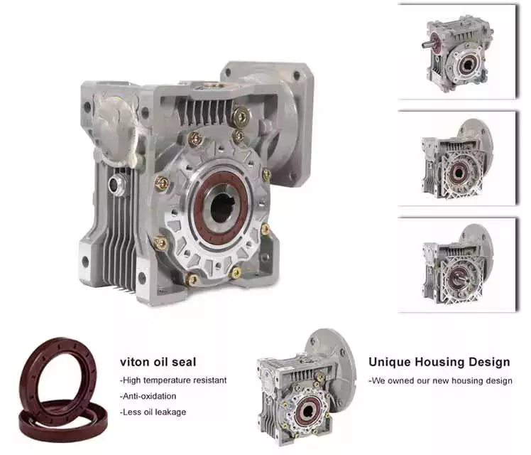
Worm gear reducer gearbox
A worm gear reducer gearbox is a mechanical device used to reduce the viscosity of fluids. It can be used in a variety of applications and is available in a variety of sizes. Read on to learn more about these devices. They come in different shapes, sizes and prices. Also, these products are very reliable.
Viscosity
A new study shows that polymers derived from worms reduce the viscosity of aqueous solutions. The researchers mixed the worms with water and then applied shearing force to the mixture. Polymer-filled solutions are more resistant to shear forces than simple liquids. This is because when the solution is sheared, the filaments become entangled with each other. When the solution is sheared, the filaments line up, reducing the viscosity of the solution.
The researchers then used live insects to study the polymer’s shear thinning properties. By measuring “worm activity”, the researchers could calculate the viscosity of the mixture. The researchers then altered the worms’ activity and measured changes in the viscosity of the mixture.
The PSMA13 precursor was synthesized from BzMA at 90 °C. The resulting PSMA13-PBzMA65 worms were studied using SAXS, 1H NMR and TEM. They were found to be highly anisotropic over a wide temperature range.
The efficiency of a worm gear reducer gearbox increases with the number of revolutions of the input shaft. Braking torque also increases with the viscosity of the oil. These three factors are used to determine the efficiency of a worm gear reducer gearbox. A worm gear reducer gearbox with a helical pinion on the motor shaft will achieve a 40:1 gear ratio. The combination of a 4 liter ratio helical primary gear with a 10:l worm secondary gear will achieve high efficiency and overload capability.
The PSMA13-PBzMA65 dispersion has the same effective viscosity at 20 degrees Celsius and variable temperature. The transition time is 0.01 Pa s, indicating good thermal reversibility.
Self-locking function
Worm reducer gearboxes have many advantages. This gear has a high capacity and can transmit a lot of power. It’s also very quiet. Its advantages also include a space-saving design. Another benefit of worm reducer gearboxes is their ease of lubrication and cooling. It is also an excellent choice for transmitting high power with high gear ratios.
The self-locking function of the worm gear unit ensures that torque is only transmitted in one direction. When the load peaks, the torque signal is disabled. Unlike conventional gear reducer gearboxes, self-locking worm gears are not interchangeable.
Self-locking worm gears are not suitable for high mass applications because the weight of the driven mass can overwhelm the gear. The large mass can cause a huge side load on the worm, which can cause the worm to break. To solve this problem, a self-locking worm gear train with special provisions can be designed to reduce the heat generated.
The self-locking properties of worm reducer gearboxes are helpful in many industrial applications. It prevents reversing, which saves money on the braking system. It can also be used to lift and hold loads. The self-locking function is very useful in preventing backing.
The self-locking function depends on the pitch diameter and lead angle. A larger pitch diameter will make the self-locking function easier. However, the lead angle decreases as the pitch diameter increases. The higher pitch diameter will also make the worm reducer gearbox more resistant to backlash.
Self-locking worm gears are also useful in lifting and hoisting applications. If the worm gear is self-locking, it cannot reverse its direction without positive torque.s This makes the worm gear ideal for applications where the worm must be lowered.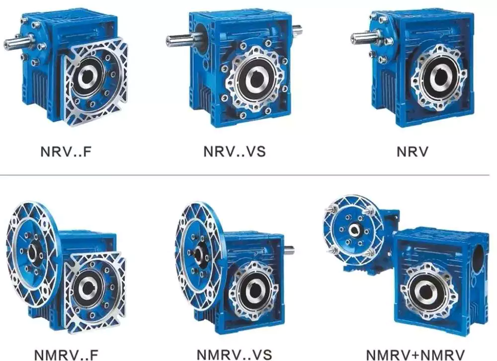
application
The worm gear reducer gearbox market is a global industry consisting of several sub-sectors. This report analyzes past and current market trends and discusses key challenges and opportunities in this market. It also highlights leading marketing players and their marketing strategies. Furthermore, the report covers important segments and provides information on emerging segments.
Worm reducer gearboxes can be used in a variety of applications, such as reducing the speed and torque of rotating parts. These gears are usually available as gear sets and seat units and are available in multi-speed designs. Some manufacturers also offer precision worms and zero-backlash worms for high precision reduction.
Typically, worm gears are used on vertical axes that do not intersect. Compared to other gear drives, they are inefficient but produce a lot of reduction. There are two basic types of worm gears: double envelope and single envelope. The difference is in how they work. When the two axes do not intersect, a double-enveloping worm gear is used.
In the industrial world, worm gear reducer gearboxes are the most popular type of reducer gearbox. They are known for their high torque output multipliers and high reduction ratios. They are used in many power transmission applications including elevators, safety gates, and conveyor belts. They are especially suitable for low to medium-horsepower applications.
Worm gears can also be used for noise control. Its unique shape and size make it suitable for tight spaces. They are also suitable for conveying heavy materials and the packaging industry. In addition, they have high gear ratios, which make them suitable for small and compact machinery.
cost
The cost of a worm gear reducer gearbox depends on several factors, including the type of worm used, the materials used to manufacture the equipment, and the number of users. The worm gear reducer gearbox market is divided into two types: vertical and horizontal. Furthermore, the market is segmented by application, including the automotive industry, shipping industry, and machinery and equipment.
Worm gear reducer gearbox is a popular type of reducer gearbox. They are available in standard and flush-type packaging. They feature C-side inputs for standard NEMA motors and multiple mounting positions to suit the application. For example, a soup factory can use the same hollow reducer gearbox in multiple installation locations.
Another application for worm gear reducer gearboxes is in conveyors. They provide torque and speed reduction to move products efficiently. They are also widely used in security doors that automatically lock when they are closed. Typically, these doors use two separate worm drives. In this way, they cannot be reversed.
The cost of a worm gear reducer gearbox is determined by several factors. Size and material are important. Worm gear reducer gearboxes can be made of aluminum, cast iron, or stainless steel. Its efficiency depends on its size and proportions. It is usually used as a retarder in low-speed machinery, but can also be used as a secondary braking device.
There are two types of worms: standard worm and double worm gear. Standard worms have one or two threads, and double worm gears have one left-hand and right-hand thread. A single-threaded combination will give you a 50 reduction ratio, while a dual-threaded combination will only give you a 25% reduction.
manufacturing
Agknx Transmission Ltd. manufactures premium worm gear reducer gearboxes with robust construction and premium case-hardened steel worms. They use phosphor bronze centrifugally cast rims and attach them to the output shaft in the center. They also feature dual-purpose bearings and a large overhang load margin on the output shaft. The high-quality reducer gearbox also has a full range of positive lubrication functions. This means that they do not need special attention when using low-speed shaft extensions.

editor by CX 2023-04-26
China Best Sales Right Angle Helical Worm Gearbox with IEC Motor worm gearbox components
Product Description
Product Description
Product Description
-S Series Helical gearbox
Product Features
1.High modular design.
2.Integrated casting housing,compact dimension,high loading support, stable transmitting and low noise level.
3.With the special gear geometry, it gets high torque, efficiency and long life circle.
4.It can achieve the direct combination for 2 sets of gearbox.
5.High efficiency and save power.
6.Save cost and low maintenance.
Product Parameters
1. Technical data
| Size | 38 | 48 | 58 | 68 | 78 | 88 | 98 |
| Structure | BS BSA BSF BSAF BSAT BSAZ | ||||||
| Input Power(kW) | 0.18~0.75 | 0.18~1.5 | 0.18~3 | 0.25~5.5 | 0.55~7.5 | 0.75~15 | 1.5~22 |
| Ratio | 10.27~165.71 | 11.46~244.74 | 10.78~196.21 | 11.55~227.20 | 9.96~241.09 | 11.83~223.26 | 12.75~230.48 |
| Permissible Torque(N.m) | 90 | 170 | 300 | 520 | 1270 | 2280 | 4000 |
| Weight(kg) | 7 | 10 | 14 | 26 | 50 | 100 | 170 |
2: Design option
| S series gear units are available in the following designs | |
| S…Y… | Foot-mounted parallel shaft helical gear units with solid shaft |
| SA…Y… | Parallel shaft helical gear units with hollow shaft |
| SAZ…Y… | Short-flange mounted parallel shaft helical gear units with hollow shaft |
| SF…Y… | Flange-mounted parallel shaft helical gear units with solid shaft |
| SAT…Y… | Flange-mounted parallel shaft helical gear units with hollow shaft |
| S(SF,SA,SAF,SAZ)S… | Shaft input parallel shaft helical gear units |
| S(SF,SA,SAF,SAZ)…R…Y… | Combinatorial parallel shaft helical gear units |
| S(SF,SA,SAF,SAZ)S…R… | Shaft input combinatorial parallel shaft helical gear units |
Materials Data Sheet
|
Housing material |
Grey Cast iron |
|
Housing hardness |
HBS163~255 |
|
Gear material |
20CrMnTi alloy steel |
|
Surface hardness of gears |
HRC58°~62 ° |
|
Gear core hardness |
HRC33~48 |
|
Input / Output shaft material |
40Cr alloy steel |
|
Input / Output shaft hardness |
HRC32~36 |
|
Machining precision of gears |
accurate grinding, 6~5 Grade |
|
Lubricating oil |
GB L-CKC220-460, Shell Omala220-460 |
|
Heat treatment |
tempering, cementiting, quenching, normalizing, etc. |
|
Efficiency |
94%~96% (depends on the transmission stage) |
|
Noise (MAX) |
60~68dB |
|
Temp. rise (MAX) |
40°C |
|
Temp. rise (Oil)(MAX) |
50°C |
|
Vibration |
≤20µm |
|
Backlash |
≤20Arcmin |
|
Brand of bearings |
China top brand bearing, HRB/LYC/ZWZ/C&U. Or other brands requested, SKF, FAG, INA, NSK. |
|
Brand of oil seal |
NAK — ZheJiang or other brands requested |
Detailed Photos
Our process of production
Our product line
Company Profile
Company Profile
Bode was founded in 2007, which is located in HangZhou city, ZHangZhoug province. As 1 professional manufacturer and exporter, we have more than 17 years’ experience in R & D of worm reducer, gear reducer, gearbox , AC motor and relative spare parts. We have factory with advanced production and test equipment, the strong development of team and producing capacity offer our customers with high quality products. Our products widely served to various industries of Metallurgy, Chemicals, lifting, mining, Petroleum, textile, medicine, wooden etc. Main markets: China, Africa, Australia, Vietnam, Turkey, Japan, Korea, Philippines… Welcome to ask us any questions, good offer always for you for long term business.
FAQ
Q1: Are you trading company or manufacturer?
A: We are factory.
Q2: What kinds of gearbox can you produce for us?
A: Main products of our company: R, S, K, F series helical-tooth reducer, RV series worm gear reducer,H Series Parallel Shaft Helical Reduction Gear Box
Q3: Can you make as per custom drawing?
A: Yes, we offer customized service for customers.
Q4: Can we buy 1 pc of each item for quality testing?
A: Yes, we are glad to accept trial order for quality testing.
Q5: What information shall we give before placing a purchase order?
A: a) Type of the gearbox, ratio, input and output type, input flange, mounting position, and motor informationetc.
b) Housing color.
c) Purchase quantity.
d) Other special requirements.
Q6: How long is your delivery time?
A: Generally it is 5-10 days if the goods are in stock. or it is 15-20 days if the goods are not in stock.
Q7: What is your terms of payment ?
A: 30% Advance payment by T/T after signing the contract.70% before delivery
If you are interested in our product, welcome to contact with us.
Our team will do our best to meet your need 🙂
| Application: | Motor, Machinery, Marine, Agricultural Machinery |
|---|---|
| Function: | Distribution Power, Change Drive Torque, Speed Changing, Speed Reduction |
| Layout: | Coaxial |
| Hardness: | Hardened Tooth Surface |
| Installation: | Horizontal Type |
| Step: | Double-Step |
| Samples: |
US$ 90/Piece
1 Piece(Min.Order) | |
|---|
| Customization: |
Available
|
|
|---|
Worm gear reducer gearbox
A worm gear reducer gearbox is a gear reducer gearbox that uses a worm gear train to reduce the required force. Unlike traditional gear reducer gearboxes, these units are small and require low horsepower ratings. This reduces their efficiency, but their low cost and compact design help make up for this shortcoming. However, these gear reducer gearboxes have some drawbacks, including their tendency to lock up when reversing.
high efficiency
High-efficiency worm reducer gearboxes are ideal for applications where high performance, repeatability, and accuracy are critical. It consists of an input hypoid gear and an output hypoid bevel gear. The input worm rotates perpendicular to the output worm, so for every revolution of the input worm, the output gear makes one revolution. This arrangement reduces friction (another source of energy loss) in a high-efficiency worm gear to at least two arc minutes.
Compared with worm gear reducer gearboxes, hypoid gearmotors offer several advantages, including lower operating costs and higher efficiency. For example, hypoid gear motors can transmit more torque even at high reduction ratios. Also, they are more efficient than worm gear reducer gearboxes, which means they can produce the same output with a smaller motor.
In recent years, the efficiency of worm gear reducer gearboxes has been dramatically improved. Manufacturers have made great strides in materials, design, and manufacturing. New designs, including dual-enveloping worm gear reducer gearboxes, increase efficiency by 3 to 8 percent. These improvements were made possible through countless hours of testing and development. Worm gear reducer gearboxes also offer lower initial costs and higher overload capability than competing systems.
Worm gear reducer gearboxes are popular because they provide maximum reduction in a small package. Their compact size makes them ideal for low to medium-horsepower applications and they are reticent. They also offer higher torque output and better shock load tolerance. Finally, they are an economical option to reduce the device’s power requirements.
low noise
Low-noise worm gear reducer gearboxes are designed to reduce noise in industrial applications. This type of reducer gearbox uses fewer bearings and can work in various mounting positions. Typically, a worm reducer gearbox is a single-stage unit with only one shaft and one gear. Since there is only one gear, the noise level of the worm gear reducer gearbox will be lower than other types.
A worm gear reducer gearbox can be integrated into the electric power steering system to reduce noise. Worm reducer gearboxes can be made and from many different materials. The following three-stage process will explain the components of a low-noise worm reducer gearbox.
Worm gear reducer gearboxes can be mounted at a 90-degree angle to the input worm shaft and are available with various types of hollow or solid output shafts. These reducer gearboxes are especially beneficial for applications where noise reduction is essential. They also have fewer parts and are smaller than other types of reducer gearboxes, making them easier to install.
Worm gear reducer gearboxes are available from various manufacturers. Due to their widespread availability, gear manufacturers maintain extensive inventories of these reducer gearboxes. The worm gear ratio is standard, and the size of the worm gear reducer gearbox is universal. Also, worm gear reducer gearboxes do not need to be sized for a specific purpose, unlike other load interruptions.
A worm gear reducer gearbox is a transmission mechanism with a compact structure, large transmission ratio, and self-locking function under certain conditions. The worm gear reducer gearbox series products are designed with American technology and have the characteristics of stable transmission, strong bearing capacity, low noise, and compact structure. In addition, these products can provide a wide range of power supplies. However, these worm reducer gearboxes are prone to leaks, usually caused by design flaws.
Worm gear reducer gearboxes are available in single-stage and double-stage. The first type consists of an oil tank that houses the worm gear and bearings. The second type uses a worm gear with a sleeve for the first worm gear.
When choosing a gear reducer gearbox, it is essential to choose a high-quality unit. Improper gear selection can cause rapid wear of the worm gear. While worm gear reducer gearboxes are generally durable, their degree of wear depends on the selection and operating conditions. For example, overuse, improper assembly, or working in extreme conditions can lead to rapid wear.
Worm reducer gearboxes reduce speed and torque. Worm gears can be used to reduce the speed of rotating machines or inertial systems. Worm gears are a type of bevel gear, and their meshing surfaces have great sliding force. Because of this, worm gears can carry more weight than spur gears. They are also harder to manufacture. However, the high-quality design of the worm gear makes it an excellent choice for applications requiring high torque and high-speed rotation.
Worm gears can be manufactured using three types of gears. For large reduction ratios, the input and output gears are irreversible. However, the worm reducer gearbox can be constructed with multiple helices. The multi-start worm drive also minimizes braking effects.
Self-locking function
The worm reducer gearbox is self-locking to prevent the load from being driven back to the ground. The self-locking function is achieved by a worm that meshes with the rack and pinion. When the load reaches the highest position, the reverse signal is disabled. The non-locking subsystem back-drives the load to its original position, while the self-locking subsystem remains in its uppermost position.
The self-locking function of the worm reducer gearbox is a valuable mechanical feature. It helps prevent backing and saves the cost of the braking system. Additionally, self-locking worm gears can be used to lift and hold loads.
The self-locking worm gear reducer gearbox prevents the drive shaft from driving backward. It works with the axial force of the worm gear. A worm reducer gearbox with a self-locking function is a very efficient machine tool.
Worm gear reducer gearboxes can be made with two or four teeth. Single-ended worms have a single-tooth design, while double-ended worms have two threads on the cylindrical gear. A multi-boot worm can have up to four boots. Worm reducer gearboxes can use a variety of gear ratios, but the main advantage is their compact design. It has a larger load capacity than a cross-shaft helical gear mechanism.
The self-locking function of the worm reducer gearbox can also be used for gear sets that are not necessarily parallel to the shaft. It also prevents backward travel and allows forward travel. The self-locking function is achieved by a ratchet cam arranged around the gear member. It also enables selective coupling and decoupling between gear members.
high gear ratio
Worm reducer gearboxes are an easy and inexpensive way to increase gear ratios. These units consist of two worm gears – an input worm gear and an output worm gear. The input worm rotates perpendicular to the output worm gear, which also rotates perpendicular to itself. For example, a 5:1 worm gearbox requires 5 revolutions per worm gear, while a 60:1 worm gearbox requires 60 revolutions. However, this arrangement is prone to inefficiency since the worm gear experiences only sliding friction, not rolling friction.
High-reduction applications require many input revolutions to rotate the output gear. Conversely, low input speed applications suffer from the same friction issues, albeit with a different amount of friction. Worms that spin at low speeds require more energy to maintain their movement. Worm reducer gearboxes can be used in many types of systems, but only some are suitable for high-speed applications.
Worm gears are challenging to produce, but the envelope design is the best choice for applications requiring high precision, high efficiency, and minimal backlash. Envelope design involves modifying gear teeth and worm threads to improve surface contact. However, this type of worm gear is more expensive to manufacture.
Worm gear motors have lower initial meshing ratios than hypoid gear motors, which allows the use of smaller motors. So a 1 hp worm motor can achieve the same output as a 1/2 hp motor. A study by Agknx compared two different types of geared motors, comparing their power, torque, and gear ratio. The results show that the 1/2 HP hypoid gear motor is more efficient than the worm gear motor despite the same output.
Another advantage of the worm gear reducer gearbox is the low initial cost and high efficiency. It offers high ratios and high torque in a small package, making it ideal for low to medium-horsepower applications. Worm gear reducer gearboxes are also more shock-resistant.

editor by CX
2023-04-24
China Good quality Assembly Reduction Gear Reducer Motor Drive Wheel Right Angle Stainless Steel Self Locking Helical Application Small NEMA Winch Worm Gearbox Manufacturer with high quality
Error:获取返回内容失败,
Your session has expired. Please reauthenticate.
| Application: | Motor, Electric Cars, Motorcycle, Machinery, Marine, Agricultural Machinery, Car |
|---|---|
| Function: | Distribution Power, Clutch, Change Drive Torque, Change Drive Direction, Speed Changing, Speed Reduction, Speed Increase |
| Layout: | Coaxial |
| Hardness: | Hardened Tooth Surface |
| Installation: | Horizontal Type |
| Step: | Three-Step |
| Samples: |
US$ 9999/Piece
1 Piece(Min.Order) | |
|---|
Advantages and disadvantages of worm gear reducer gearbox
If you are looking for a worm gear reducer gearbox, you have come to the right place. This article will cover the pros and cons of worm gear reducer gearboxes and discuss the different types available. You will learn about multi-head worm gear reducer gearboxes, hollow shaft worm gear reducer gearboxes as well as hypoid gear sets and motors.
Hollow shaft worm gear reducer gearbox
Hollow shaft worm gear reducer gearboxes are used to connect two or more rotating parts. They are available in single-axis and dual-axis versions and can be connected to various motor types. They can also have different ratios. The ratios of these gear reducer gearboxes depend on the quality of the bearings and assembly process.
Hollow shaft worm gear reducer gearboxes are made of bronze worm gears and cast iron hubs. The gears are lubricated with synthetic oil. They are lightweight and durable. They can be installed in various engine housings. Additionally, these gear reducer gearboxes are available in a variety of sizes. The range includes 31.5, 40, 50, 63, and 75mm models. Other sizes are available upon request.
In addition to worm gear reducer gearboxes, there are also helical gear reducer gearboxes. These reducer gearboxes can achieve very low output speeds. They are also suitable for all-around installations. In addition, the advantage of a multi-stage reducer gearbox is that it is more efficient than a single-stage gear reducer gearbox. They also feature low noise, low vibration, and low energy consumption.
Hollow shaft worm gear reducer gearboxes are generally less expensive and last longer. They are also a suitable replacement for solid shaft gearboxes for machines that require high torque without compromising strength. Typical gear arrangements include worm, spur, helical and bevel gears. Gear ratio is the ratio of input torque to output torque.
Multi-head worm gear reducer gearbox
The multi-head worm gear reducer gearbox is used to reduce the speed of the machine. It uses friction to hold the worm in place while transmitting power. These gears can also be called ground worms and hardened worm gears. They are useful in conveying systems and most engineering applications.
Multiple worm reducer gearboxes have a large number of gear ratios. These gear designs have a central cross-section that forms the front and rear boundaries of the worm gear. This design is a better choice than other worm gears because it is less prone to wear and can be used with a variety of motors and other electronics.
Adjustable multi-head worm gear reducer gearbox to reduce axial play. Usually, the backlash on the left and right sides of the worm is the same. However, if you need less backlash, you can buy a double lead worm gear. This design is ideal for precision applications requiring small clearances. The lead of the opposing teeth of the double worm gear is different from the right side, so the backlash can be adjusted without adjusting the center distance between the worm gears.
Worm gear reducer gearboxes are available from a variety of manufacturers. Many gear manufacturers stock these gears. Since the gear ratios are standardized, there is no need to adjust the height, diameter, or length of the shaft. Worm gears have fewer moving parts, which means they require less maintenance.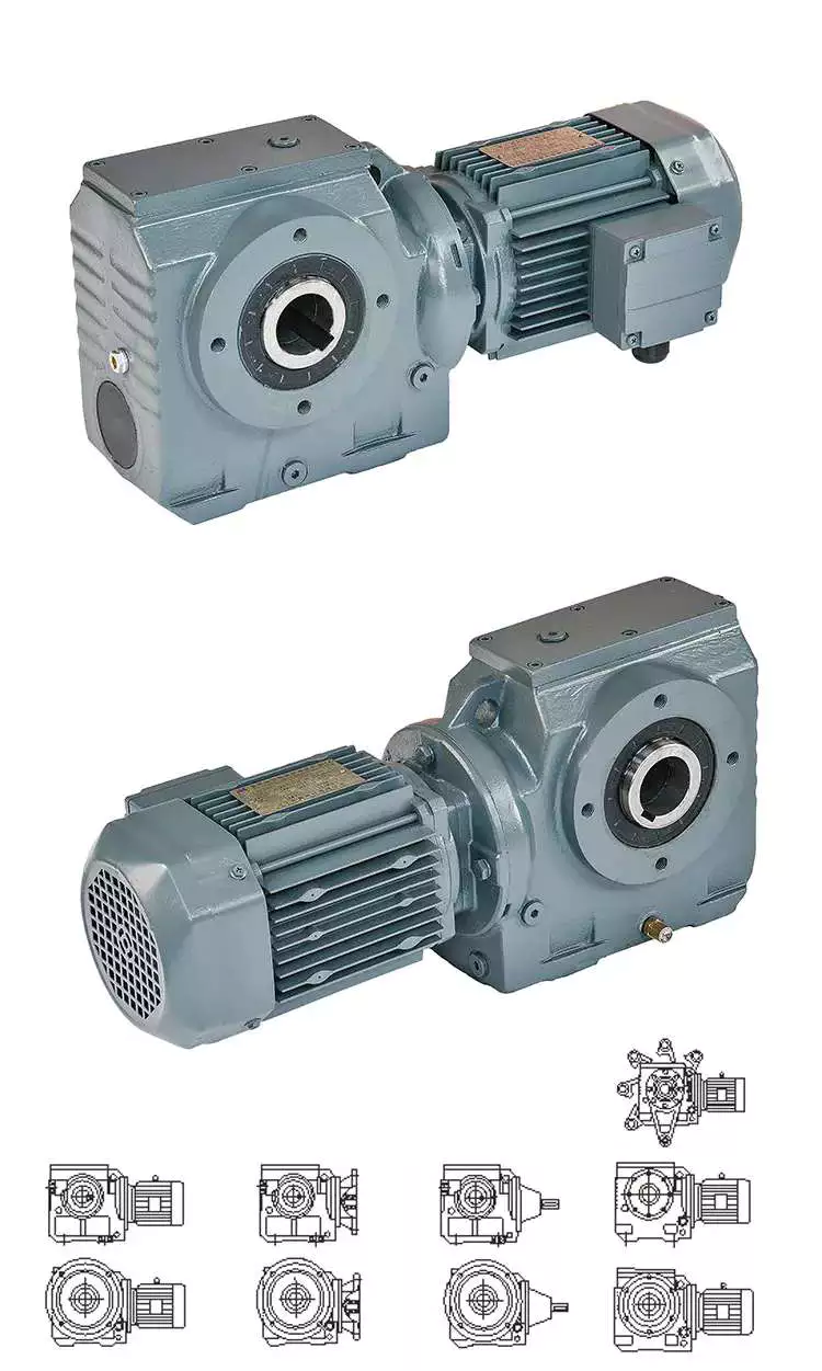
Hypoid Gear Set
Worm gears are the most common type of gear. While these gears are great for high-to-low ratios, hypoid gear sets are much more efficient in all ratios. This difference is due to higher torque density, better geometry and materials, and the way hypoid gears transmit force differently than worm gears.
Hypoid gear sets have curved helical teeth. This results in smooth gear meshing and little noise. This is because the hypoid gears start to slowly contact each other, but the contact progresses smoothly from tooth to tooth. This reduces friction and wears, thereby increasing the efficiency of the machine.
The main advantages of hypoid gears over worm gears are higher torque capacity and lower noise levels. Although their upfront cost may be higher, hypoid gears are more efficient than worm gears. They are able to handle higher initial inertia loads and can deliver more torque with a smaller motor. This saves money in the long run.
Another advantage of hypoid gears is the lower operating temperature. They also do not require oil lubrication or ventilation holes, reducing maintenance requirements. The hypoid gear set is maintenance-free, and the grease on the hypoid gear set lasts for decades.
Hypoid gear motor
A hypoid gear motor is a good choice for a worm gear reducer gearbox as it allows for a smaller motor and more efficient energy transfer. In fact, a 1 hp motor driving a hypoid reducer gearbox can provide the same output as a 1/2 hp motor driving a worm reducer gearbox. A study by Agknx compared two gear reduction methods and determined that a hypoid gear motor produces more torque and power than a worm reducer gearbox when using a fixed reduction ratio of 60:1. The study also showed that the 1/2 HP hypoid gear motor is more energy efficient and reduces electricity bills.
Worm reducer gearboxes run hotter than hypoid gears, and the added heat can shorten their lifespan. This can cause components to wear out faster, and the motor may require more frequent oil changes. In addition, hypoid gear motors are more expensive to manufacture.
Compared to worm gears, hypoid gears offer higher efficiency and lower operating noise. However, they require additional processing techniques. They are made of bronze, a softer metal capable of absorbing heavy shock loads. Worm drives require work hardening and are less durable. Operating noise is reduced by up to 30%, and hypoid gears are less prone to breakage than bevel gears.
Hypoid gear motors are prized for their efficiency and are used in applications requiring lower torque. A unique hypoid tooth profile reduces friction. In addition, hypoid gear motors are ideal for applications where space is limited. These geared motors are often used with pulleys and levers.
R series worm gear reducer gearbox
R series worm gear reducer gearboxes have a variety of characteristics that make them ideal for different applications. Its high rigidity cast iron housing and rigid side gears are designed for smooth drive and low noise. It also features high load capacity and long service life. Additionally, it can be assembled into many different configurations as required.
High efficiency, large output torque and good use efficiency. It comes in four basic models ranging from 0.12KW to 200KW. It can be matched with right angle bevel gearbox to provide large speed ratio and high torque. This combination is also suitable for low output and high torque.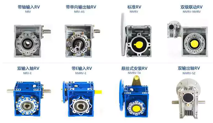
AGKNX Electric Worm Gear reducer gearbox
AGKNX Electric worm gear reducer gearboxes are available with NEMA C-face mounting flanges for a variety of motors. These reducer gearboxes feature double lip oil seals, an aluminum alloy housing, and two bearings on the input and output shafts. These reducer gearboxes are rust-proof and have epoxy paint on the inside. They are available in a variety of ratios, from 7.5:1 to 100:1.
Worm reducer gearboxes are one of the most cost-effective and compact gears. These reducer gearboxes increase output torque while reducing input speed. AGKNX Electric’s worm gear reducer gearboxes are pre-installed with Mobil SHC634 Synthetic Gear Oil. These reducer gearboxes have an internal oil gallery guide to protect the shaft. They also have a one-piece cast iron housing.
AGKNX Electric Corporation is the leading independent distributor of electric motors in the United States. They have eight strategically located warehouses, enabling them to ship most orders on the same day. They offer motors of various sizes up to 20,000 hp. They also offer a variety of motor controls and variable speed drives.

editor by CX 2023-04-23
China Three Phase 0.06-15kw AC Right Angle Gear Motor Worm Gearbox with Hot selling
Merchandise Description
Item Description
Principal Materials:
1)housing:aluminium alloy ADC12(measurement 571-090) die forged iron HT200(dimension a hundred and ten-a hundred and fifty)
two)Worm:20Cr, ZI Involute profile carbonize&quencher heat remedy make equipment surface hardness up to 56-sixty two HRC After precision grinding, carburization layer’s thickness in between .3-.5mm.
3)Worm Wheel:wearable stannum alloy CuSn10-1
Comprehensive Photos
Blend Options:
Input:with enter shaft, With square flange,With IEC normal input flange
Output:with torque arm, output flange, one output shaft, double output shaft, plastic protect
Worm reducers are available with diffferent combinations: NMRV+NMRV, NMRV+NRV, NMRV+Laptop, NMRV+UDL, NMRV+MOTORS
Exploded See:
Solution Parameters
| Previous Model |
New Model | Ratio | Center Distance | Energy | Input Dia. | Output Dia. | Output Torque | Fat |
| RV571 | 7.5~100 | 25mm | .06KW~.12KW | Φ9 | Φ11 | 21N.m | .7kgs | |
| RV030 | RW030 | 7.5~a hundred | 30mm | .06KW~.25KW | Φ9(Φ11) | Φ14 | 45N.m | one.2kgs |
| RV040 | RW040 | 7.5~one hundred | 40mm | .09KW~.55KW | Φ9(Φ11,Φ14) | Φ18(Φ19) | 84N.m | 2.3kgs |
| RV050 | RW050 | seven.5~100 | 50mm | .12KW~1.5KW | Φ11(Φ14,Φ19) | Φ25(Φ24) | 160N.m | three.5kgs |
| RV063 | RW063 | seven.5~one hundred | 63mm | .18KW~2.2KW | Φ14(Φ19,Φ24) | Φ25(Φ28) | 230N.m | 6.2kgs |
| RV075 | RW075 | 7.5~one hundred | 75mm | .25KW~4.0KW | Φ14(Φ19,Φ24,Φ28) | Φ28(Φ35) | 410N.m | nine.0kgs |
| RV090 | RW090 | seven.5~one hundred | 90mm | .37KW~4.0KW | Φ19(Φ24,Φ28) | Φ35(Φ38) | 725N.m | 13.0kgs |
| RV110 | RW110 | 7.5~a hundred | 110mm | .55KW~7.5KW | Φ19(Φ24,Φ28,Φ38) | Φ42 | 1050N.m | 35.0kgs |
| RV130 | RW130 | 7.5~one hundred | 130mm | .75KW~7.5KW | Φ24(Φ28,Φ38) | Φ45 | 1550N.m | forty eight.0kgs |
| RV150 | RW150 | 7.5~100 | 150mm | 2.2KW~15KW | Φ28(Φ38,Φ42) | Φ50 | eighty four.0kgs |
GMRV Outline Dimension:
| GMRV | A | B | C | C1 | D(H8) | E(h8) | F | G | G1 | H | H1 | I | M | N | O | P | Q | R | S | T | BL | β | b | t | V |
| 030 | eighty | ninety seven | 54 | 44 | fourteen | 55 | 32 | 56 | 63 | 65 | 29 | 55 | forty | fifty seven | 30 | 75 | forty four | 6.five | 21 | five.five | M6*10(n=4) | 0° | five | 16.3 | 27 |
| 040 | 100 | 121.5 | 70 | 60 | 18(19) | 60 | forty three | seventy one | 78 | 75 | 36.5 | 70 | 50 | seventy one.5 | forty | 87 | fifty five | 6.five | 26 | 6.5 | M6*10(n=4) | 45° | six | twenty.8(21.8) | 35 |
| 050 | one hundred twenty | a hundred and forty four | eighty | 70 | 25(24) | 70 | 49 | eighty five | 92 | eighty five | 43.5 | eighty | 60 | 84 | 50 | one hundred | 64 | 8.five | thirty | seven | M8*twelve(n=4) | 45° | eight | 28.3(27.3) | 40 |
| 063 | one hundred forty four | 174 | 100 | eighty five | 25(28) | 80 | 67 | 103 | 112 | ninety five | fifty three | 95 | 72 | 102 | 63 | a hundred and ten | 80 | eight.five | 36 | 8 | M8*12(n=8) | 45° | 8 | 28.3(31.3) | 50 |
| 075 | 172 | 205 | one hundred twenty | ninety | 28(35) | ninety five | seventy two | 112 | one hundred twenty | a hundred and fifteen | fifty seven | 112.five | 86 | 119 | 75 | 140 | ninety three | 11 | 40 | 10 | M8*14(n=8) | 45° | eight(10) | 31.3(38.3) | sixty |
| 090 | 206 | 238 | a hundred and forty | 100 | 35(38) | 110 | seventy four | one hundred thirty | a hundred and forty | a hundred thirty | 67 | 129.five | 103 | one hundred thirty five | 90 | one hundred sixty | 102 | thirteen | 45 | eleven | M10*16(n=8) | 45° | ten | 38.3(41.3) | 70 |
| 110 | 255 | 295 | a hundred and seventy | 115 | forty two | a hundred thirty | – | 144 | one hundred fifty five | one hundred sixty five | seventy four | one hundred sixty | 127.five | 167.5 | a hundred and ten | two hundred | one hundred twenty five | fourteen | fifty | fourteen | M10*18(n=8) | 45° | 12 | 45.three | eighty five |
| a hundred thirty | 293 | 335 | two hundred | one hundred twenty | 45 | a hundred and eighty | – | one hundred fifty five | 170 | 215 | 81 | 179 | 146.5 | 187.five | 130 | 250 | a hundred and forty | sixteen | 60 | 15 | M12*twenty(n=8) | 45° | fourteen | forty eight.eight | one hundred |
| 150 | 340 | four hundred | 240 | a hundred forty five | fifty | a hundred and eighty | – | 185 | 200 | 215 | ninety six | 210 | 170 | 230 | 150 | 250 | one hundred eighty | eighteen | 72.5 | eighteen | M12*22(n=8) | 45° | 14 | fifty three.8 | 120 |
Business Profile
About CZPT Transmission:
We are a professional reducer manufacturer located in HangZhou, ZHangZhoug province.
Our top items is full variety of RV571-a hundred and fifty worm reducers , also supplied GKM hypoid helical gearbox, GRC inline helical gearbox, Pc units, UDL Variators and AC Motors, G3 helical equipment motor.
Items are extensively utilized for apps this kind of as: foodstuffs, ceramics, packing, chemical compounds, pharmacy, plastics, paper-generating, construction equipment, metallurgic mine, environmental defense engineering, and all kinds of automated strains, and assembly strains.
With quickly shipping, exceptional right after-income services, sophisticated creating facility, our items offer well both at residence and overseas. We have exported our reducers to Southeast Asia, Eastern Europe and Middle East and so on.Our goal is to develop and innovate on basis of higher quality, and produce a good popularity for reducers.
Packing info:Plastic Baggage+Cartons+Wooden Situations , or on ask for
We take part Germany Hannver Exhibition-ZheJiang PTC Honest-Turkey Earn Eurasia
Logistics
Following Product sales Support
1.Servicing Time and Warranty:In 1 yr after obtaining goods.
2.Other Support: Like modeling variety guidebook, set up guidebook, and issue resolution guidebook, etc.
FAQ
1.Q:Can you make as for each customer drawing?
A: Yes, we supply tailored support for clients appropriately. We can use customer’s nameplate for gearboxes.
two.Q:What is your phrases of payment ?
A: 30% deposit just before generation,balance T/T just before delivery.
3.Q:Are you a trading organization or maker?
A:We are a manufacurer with superior products and experienced staff.
four.Q:What is your generation potential?
A:8000-9000 PCS/Month
5.Q:Free sample is offered or not?
A:Of course, we can supply free sample if buyer concur to pay for the courier price
6.Q:Do you have any certificate?
A:Of course, we have CE certificate and SGS certification report.
Speak to info:
Ms Lingel Pan
For any queries just truly feel totally free ton get in touch with me. Numerous many thanks for your kind interest to our organization!
|
/ Piece | |
1 Piece (Min. Order) |
###
| Application: | Motor, Machinery, Marine, Agricultural Machinery, Industry |
|---|---|
| Function: | Distribution Power, Change Drive Torque, Speed Changing, Speed Reduction |
| Layout: | Right Angle |
| Hardness: | Hardened Tooth Surface |
| Installation: | Horizontal Type |
| Step: | Double-Step |
###
| Samples: |
US$ 12/Piece
1 Piece(Min.Order) |
|---|
###
| Customization: |
|---|
###
| Old Model |
New Model | Ratio | Center Distance | Power | Input Dia. | Output Dia. | Output Torque | Weight |
| RV025 | 7.5~100 | 25mm | 0.06KW~0.12KW | Φ9 | Φ11 | 21N.m | 0.7kgs | |
| RV030 | RW030 | 7.5~100 | 30mm | 0.06KW~0.25KW | Φ9(Φ11) | Φ14 | 45N.m | 1.2kgs |
| RV040 | RW040 | 7.5~100 | 40mm | 0.09KW~0.55KW | Φ9(Φ11,Φ14) | Φ18(Φ19) | 84N.m | 2.3kgs |
| RV050 | RW050 | 7.5~100 | 50mm | 0.12KW~1.5KW | Φ11(Φ14,Φ19) | Φ25(Φ24) | 160N.m | 3.5kgs |
| RV063 | RW063 | 7.5~100 | 63mm | 0.18KW~2.2KW | Φ14(Φ19,Φ24) | Φ25(Φ28) | 230N.m | 6.2kgs |
| RV075 | RW075 | 7.5~100 | 75mm | 0.25KW~4.0KW | Φ14(Φ19,Φ24,Φ28) | Φ28(Φ35) | 410N.m | 9.0kgs |
| RV090 | RW090 | 7.5~100 | 90mm | 0.37KW~4.0KW | Φ19(Φ24,Φ28) | Φ35(Φ38) | 725N.m | 13.0kgs |
| RV110 | RW110 | 7.5~100 | 110mm | 0.55KW~7.5KW | Φ19(Φ24,Φ28,Φ38) | Φ42 | 1050N.m | 35.0kgs |
| RV130 | RW130 | 7.5~100 | 130mm | 0.75KW~7.5KW | Φ24(Φ28,Φ38) | Φ45 | 1550N.m | 48.0kgs |
| RV150 | RW150 | 7.5~100 | 150mm | 2.2KW~15KW | Φ28(Φ38,Φ42) | Φ50 | 84.0kgs |
###
| GMRV | A | B | C | C1 | D(H8) | E(h8) | F | G | G1 | H | H1 | I | M | N | O | P | Q | R | S | T | BL | β | b | t | V |
| 030 | 80 | 97 | 54 | 44 | 14 | 55 | 32 | 56 | 63 | 65 | 29 | 55 | 40 | 57 | 30 | 75 | 44 | 6.5 | 21 | 5.5 | M6*10(n=4) | 0° | 5 | 16.3 | 27 |
| 040 | 100 | 121.5 | 70 | 60 | 18(19) | 60 | 43 | 71 | 78 | 75 | 36.5 | 70 | 50 | 71.5 | 40 | 87 | 55 | 6.5 | 26 | 6.5 | M6*10(n=4) | 45° | 6 | 20.8(21.8) | 35 |
| 050 | 120 | 144 | 80 | 70 | 25(24) | 70 | 49 | 85 | 92 | 85 | 43.5 | 80 | 60 | 84 | 50 | 100 | 64 | 8.5 | 30 | 7 | M8*12(n=4) | 45° | 8 | 28.3(27.3) | 40 |
| 063 | 144 | 174 | 100 | 85 | 25(28) | 80 | 67 | 103 | 112 | 95 | 53 | 95 | 72 | 102 | 63 | 110 | 80 | 8.5 | 36 | 8 | M8*12(n=8) | 45° | 8 | 28.3(31.3) | 50 |
| 075 | 172 | 205 | 120 | 90 | 28(35) | 95 | 72 | 112 | 120 | 115 | 57 | 112.5 | 86 | 119 | 75 | 140 | 93 | 11 | 40 | 10 | M8*14(n=8) | 45° | 8(10) | 31.3(38.3) | 60 |
| 090 | 206 | 238 | 140 | 100 | 35(38) | 110 | 74 | 130 | 140 | 130 | 67 | 129.5 | 103 | 135 | 90 | 160 | 102 | 13 | 45 | 11 | M10*16(n=8) | 45° | 10 | 38.3(41.3) | 70 |
| 110 | 255 | 295 | 170 | 115 | 42 | 130 | – | 144 | 155 | 165 | 74 | 160 | 127.5 | 167.5 | 110 | 200 | 125 | 14 | 50 | 14 | M10*18(n=8) | 45° | 12 | 45.3 | 85 |
| 130 | 293 | 335 | 200 | 120 | 45 | 180 | – | 155 | 170 | 215 | 81 | 179 | 146.5 | 187.5 | 130 | 250 | 140 | 16 | 60 | 15 | M12*20(n=8) | 45° | 14 | 48.8 | 100 |
| 150 | 340 | 400 | 240 | 145 | 50 | 180 | – | 185 | 200 | 215 | 96 | 210 | 170 | 230 | 150 | 250 | 180 | 18 | 72.5 | 18 | M12*22(n=8) | 45° | 14 | 53.8 | 120 |
Worm reducer gearbox – What You Need to Know
When shopping for a Worm reducer gearbox, it is important to consider the functions and features of the unit. It is also important to take into account its cost. We will take a look at the different types of worm reducer gearboxes and the applications that they can be used for. This will help you choose the right unit for your application.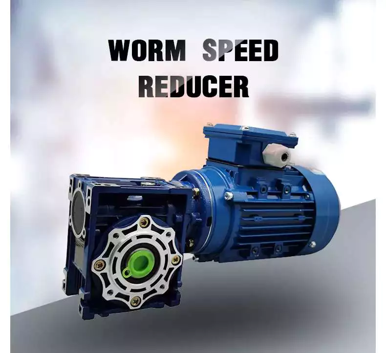
Features
Worm gears are popular in instruments that require fast stopping, such as elevators and lifts. Their soft materials allow them to absorb shock, which reduces the likelihood of failure. They are also beneficial in heavy-duty machines, such as rock crushers. Some manufacturers offer special worms with zero backlash and high-accuracy reduction.The worm reducer gearbox has a variety of features, including an axial pitch and a circular pitch. The axial pitch of the worm must match the circular pitch of the larger gear. Its threads are left or right-handed, and its lead angle is the distance a point on the thread travels during a revolution of the worm.The worm gear reducer gearbox is widely available, and gear manufacturers typically maintain a large inventory of them. Because worm gears are standardized, their mounting dimensions are generally uniform across manufacturers. This means that choosing one will not require you to change the height, length, or diameter of the output shaft. Worm gear reducer gearboxes also have dimensional consistency.Worm gears are very efficient. They have a high load capacity and a low friction coefficient. The worm gears also have a precise tooth profile, which reduces speed fluctuations and allows for quiet operation.
Functions
Worm gears have different functions. They can be used in a variety of applications. For instance, they can be used in elevators to reduce the load on the elevator. These gears also have low noise levels because they are made of dissimilar metals. Moreover, these gears can be used in elevators because they are suitable for this type of application. However, they need a single stage reducer gearbox to function properly.Another important feature of a worm reducer gearbox is that it can operate in reverse. This means that the input shaft turns backwards, while the output shaft rotates forwards. Examples of such applications include hand-cranked centrifuges, blacksmithing forge blowers, and the wind governor of musical boxes. Worm gears are available in different shapes and sizes, from gearsets to housed units. They can also be configured as multi-speed designs. Some manufacturers also offer special precision and zero-backlash worms.A worm reducer gearbox’s tooth form is important in determining the capacity of the device. Typically, a single-lead worm gear has the same lead on the left and right tooth surfaces, although a dual-lead worm gear has different leads on each side. This feature helps to eliminate play in the worm gear. However, it is important to note that a worm reducer gearbox can be manufactured with different tooth shapes for different applications.The worm gear is an alternative to conventional gears. It operates in a similar fashion to ordinary gear drives. The main advantage of a worm gear is that it is able to reduce the rotational speed and torque of a rotating shaft. It also has the added benefit of being able to transfer motion at an angle of 90 degrees. The only drawback of a worm gear is that it cannot reverse motion.
Applications
This market report analyzes the Worm reducer gearbox market from a global perspective. It includes a comprehensive analysis of the current market trends and future growth prospects. It also provides information about the competitive landscape and the main players in the industry. The report also highlights the key factors affecting the growth of the Worm reducer gearbox market.
The major regional markets for the Worm reducer gearbox include North America, Asia-Pacific, the Middle East and Africa, Latin America, and Europe. The market in these regions is likely to remain stable with a limited growth over the next few years. A worm gear is a small mechanical device that is connected to a larger gear. When connected together, it produces a low output speed but high torque.The gearing on a worm drive can be right-hand or left-hand, and can turn clockwise or counter-clockwise. Depending on the worm’s helix angles, back-driving and friction can be reduced. Worm gears are available in housed units or in gearsets. Some manufacturers offer integrated servomotors and multi-speed designs. High-accuracy and zero-backlash worms are available.Worm gears are particularly popular in instruments that require fast stops. They are also commonly found in elevators and lifts. Their soft nature and low-shock characteristics make them highly suitable for these types of machines.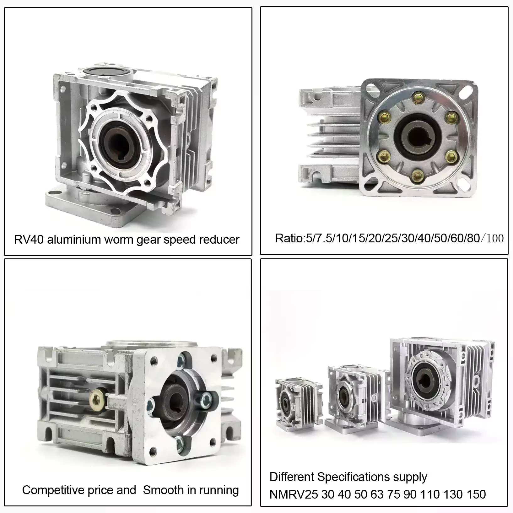
Cost
Cost is an important consideration when selecting a worm reducer gearbox. The initial cost of a worm gear reducer gearbox is considerably lower than other types of gear reducer gearboxes. Worm gear reducer gearboxes are also more energy-efficient, and have higher overload capacities than competitive systems. The following are factors that affect the cost of a worm gear reducer gearbox.Stainless steel worm gear reducer gearboxes from Agknx offer great value for the money. They offer flange input and hollow output bore sizes, as well as center distances ranging from 1.75″ to 3.25″. In addition to the standard version, a stainless steel bushing kit is available, which allows users to use a wider range of head shaft sizes. Stainless steel worm gear reducer gearboxes are available in stock from all six of Agknx’s regional warehouses. They also come with free prepaid freight.Worm gear reducer gearboxes are often used in power transmission systems, elevators, conveyor belts, and medical equipment. In these applications, they are used to control the speed of a load and prevent it from freefall. While worm gear reducer gearboxes are not as efficient as helical gearboxes, they are still very useful for applications that require high torque or high output rates.To select the right type of worm for your application, you should consider the number of teeth it contains. It’s best to select worms with a combined total of 40 teeth or more.
aspect
Worm reducer gearboxes vary in size. They have one, two or more threads. Each thread has a lead angle. A high ratio has more teeth than a low gear, and a low ratio has fewer teeth. These differences are the result of gearing. The size of the worm gear reducer gearbox should be selected according to the specific application.The worm gear reducer gearbox saves space and provides more torque. Agknx Gearbox has created a variety of models to overcome common deceleration challenges, from standard to hygienic markets. The superior transmission Agknx range is designed to solve common deceleration challenges and expand to meet the needs of the sanitary industry.The diameter of the worm reducer gearbox is an important consideration. Its diameter should be equal to or slightly larger than the diameter of the grinding wheel or tool. This will affect the pressure angle. The pressure angle on a worm reducer gearbox depends on several factors, including its diameter and lead angle. The diameter of the grinding wheel or tool also has an effect on the profile of the worm.Worm gear reducer gearboxes are common. Many gear manufacturers have large stocks of these gear reducer gearboxes. Since gears are standardized, the mounting dimensions of worm gears are also common among manufacturers. This makes it easy to select a worm gear reducer gearbox for your application. In addition, the worm gear reducer gearbox is easy to install and maintain.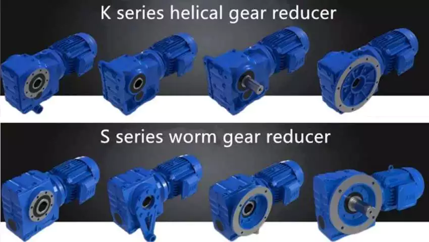
Worm gear reducer gearbox oil
Worm gear reducer gearboxes usually use gear oil. Several types of gear oils are available, including synthetic, polyalkylene glycol, and mineral oils. The oil used in the worm gear reducer gearbox must have the right viscosity for the gear. Some oils are more corrosive than others and should be avoided if the environment is toxic.The oil of the worm gear reducer gearbox must be protected against corrosion, wear and friction. It is best to choose a lubricant with low friction rate, high oxidation resistance and good anti-wear protection. While mineral oils are the most common type of lubricant, synthetic base oils can improve gear efficiency and reduce operating temperatures. This is because the Arrhenius rate rule states that the chemical reaction in the oil doubles for every 10 degrees Celsius increase in temperature.Worm gear reducer gearboxes are available in a variety of sizes and configurations. They are suitable for all kinds of machines and equipment. The sliding action between the worm gear and the output shaft produces high torque and high efficiency. If the transmission speed is low, the worm gear and output shaft can be combined for maximum efficiency.Worm gear reducer gearboxes require less frequent oil changes than other types of gear reducer gearboxes. However, regular oil should be changed every six months or 2,500 hours, whichever comes first. Also, it is a good idea to regularly monitor the oil level to prevent lubrication-related gearbox failures. It’s also wise to use synthetic oil, as it will last longer between oil changes.


editor by CX 2023-04-14
china supplier 24V DC Worm Gear Right Angle Brush Gear Motor manufacturers
Solution Description
24V DC Worm Equipment Appropriate CZPT le Brush Gear CZPT
Product Description:
Equipment CZPT -Torque Desk Allowance Torque Device:Upside (N.m)/Belowside (kgf.cm)
•Gearhead and Intermediate gearhead are marketed separately.
•Enter the reduction ratio into the blank() in the design title.
•The pace is calculated by dividing the motor’s synchronous pace by the reduction ratio. The real speed is 2%~twenty% considerably less than the shown benefit, based on the dimensions of the load.
•To decrease the pace past the reduction ratio in the adhering to table, attach an intermediate gearhead (reduction ratio: ten) between the reducer and motor. In that circumstance, the permissible torque is 8N-m.
|
Type Motor/Gearhead |
Equipment Ratio |
three |
3.6 |
five |
6 |
7.five |
9 |
twelve.five |
15 |
eighteen |
twenty five |
thirty |
36 |
fifty |
sixty |
seventy five |
90 |
a hundred |
a hundred and twenty |
a hundred and fifty |
a hundred and eighty |
|
Velocity r/min |
a thousand |
833 |
600 |
five hundred |
400 |
333 |
240 |
200 |
166 |
120 |
a hundred |
eighty three |
sixty |
fifty |
forty |
33 |
30 |
25 |
twenty |
16 |
|
| Z4D120-24GN(4GN25RC) |
4GN()RC/ 4GN()RT |
.25 |
.thirty |
.forty two |
.fifty |
.70 |
.eighty four |
one.16 |
one.39 |
1.67 |
two.32 |
two.78 |
three.34 |
four.sixty four |
five.01 |
6.27 |
7.fifty two |
eight.00 |
8.00 |
eight.00 |
8.00 |
|
two.55 |
three.06 |
4.28 |
5.10 |
7.fourteen |
eight.57 |
eleven.8 |
fourteen.2 |
17. |
23.7 |
28.4 |
34.one |
forty seven.three |
fifty one.1 |
64. |
76.seven |
eighty. |
eighty. |
80. |
8.00 |
Dimensions(Unit:mm):
Company Information
FAQ
Q: What’re your major items?
A: We presently generate Brushed Dc CZPT s, Brushed Dc Gear CZPT s, Planetary Dc Equipment CZPT s, Brushless Dc CZPT s, Stepper motors, Ac CZPT s and CZPT CZPT Planetary Gear Box and so forth. You can verify the technical specs for previously mentioned motors on CZPT website and you can electronic mail us to recommend required motors for each your specification also.
Q: How to choose a suited motor?
A:If you have motor pictures or drawings to demonstrate us, or you have in depth specs like voltage, pace, torque, motor dimension, doing work mode of the motor, needed life span and sounds amount and many others, make sure you do not wait to permit us know, then we can advise ideal motor for every your ask for appropriately.
Q: Do you have a CZPT ized provider for your common motors?
A: Of course, we can CZPT ize for each your ask for for the voltage, pace, torque and shaft measurement/form. If you want additional wires/cables soldered on the terminal or need to incorporate connectors, or capacitors or EMC we can make it as well.
Q: Do you have an specific design service for motors?
A: Of course, we would like to layout motors separately for CZPT CZPT ers, but it may want some mildew creating expense and style charge.
Q: What is your guide time?
A: Typically talking, CZPT normal normal solution will require 15-30days, a bit CZPT er for CZPT ized products. But we are very flexible on the direct time, it will depend on the distinct orders.
Remember to speak to us if you have detailed requests, thank you ()
EP also sells gear tooth measuring units named equipment gauges! Equipment gauges reduce glitches, preserving time and funds when identifying and purchasing gears. These pitch templates have 9 teams to decide all regular pitch measurements: Diameter Pitch “DP”, Circle Pitch “CP”, Exterior Involute Spline, Metric Modulus “MOD”, Brief Tooth, Fantastic Pitch, Coarse Pitch and Incredible Pitch .
china sales DC AC Right Angle Worm Gear Motor for Telescopic Retractable Roller Shutter Volume Roll Sliding Gate Rolling Garage Door manufacturers
Solution Description
DC AC Correct CZPT le Worm Equipment CZPT for Telescopic Retractable Roller Shutter Quantity Roll Sliding Gate Rolling Garage Door
Features:
1) Dimensions: 60*60mm
2) CZPT : 15W 20W
3) Voltage: 12V 24V 48V 90V 310V
four) Rated pace: 2000rpm, 3000rpm
five) Reduction ratio: 3~ 200K
Product photograph:
Specification for DC gear motor:
| Motor variety | Brush type / Brushless sort / Stepper sort | ||
| Frame dimension | 16mm ~ 130mm… can be CZPT ized | ||
| Operating velocity | Motor 1500-4000 rpm, Equipment Ratio 1/3 ~ 1/3000 | ||
| Output CZPT | 3W ~2200W… can be CZPT ized | ||
| Output shaft | round shaft, D-reduce shaft, essential-way shaft, hollow shaft… | ||
| Voltage kind | 12V / 24V / 36V / 48V / 90V / 110V /220V… can be CZPT ized | ||
| Add-ons | Internal driver / External driver / Connector / Brake / Encoder… | ||
| Gearbox type | Parallel shaft | ||
| Correct angle hollow worm shaft | Correct angle bevel hollow shaft | Flat kind hollow shaft | |
| Right angle solid worm shaft | Proper angle bevel solid shaft | Flat sort reliable shaft | |
| Planetary center shaft | |||
FAQ
Q: Can you make the gear motor with CZPT ization?
A: Sure, we can CZPT ize for each your request, like CZPT , voltage, speed, shaft size, wires, connectors, IP quality, etc.
Q: Do you supply samples?
A: Yes. Sample is CZPT for screening.
Q: What is your MOQ?
A: It is 10pcs for the starting of CZPT enterprise.
Q: What’s your lead time?
A: Standard solution require 5-30days, a bit CZPT er for CZPT ized merchandise.
Q: Do you supply engineering help?
A: Yes. Our firm have style and advancement staff, we can offer technological innovation support if you
need to have.
Q: How to ship to us?
A: It is CZPT by air, or by sea, or by prepare.
Q: How to spend the cash?
A: T/T and L/C is favored, with various forex, like USD, EUR, RMB, etc.
Q: How can I know the product is suitable for me?
A: >1ST validate drawing and specification >2nd take a look at sample >3rd commence mass generation.
Q: Can I appear to your organization to check out?
A: Indeed, you are welcome to go to us at any time.
Q: How shall we contact you?
A: You can send inquiry directly, and we will respond inside 24 hrs.
The efficiency of a worm equipment transmission relies upon to a huge extent on the helix angle of the worm. Multi-threaded worms and gears with higher helix angles have proven to be 25% to fifty% much more successful than one-threaded worms. The sliding action of the worm meshing with or meshing with the worm gear final results in appreciable friction and decline of efficiency in contrast to other types of gears. Improve performance with hardened and floor worm switch bronze worm gears.
